Integrated micromachined thermal mass flow sensor and methods of making the same

a micro-machined, sensor technology, applied in the direction of volume/mass flow by differential pressure, liquid/fluent solid measurement, instruments, etc., can solve the problems of high manufacturing cost of identical sensors, inaccurateness, and difficulty in measuring flows above a certain flow velocity, and achieve good thermal isolation and high sensitivity

Active Publication Date: 2009-06-25
M TECH INSTR HLDG
View PDF3 Cites 50 Cited by
  • Summary
  • Abstract
  • Description
  • Claims
  • Application Information

AI Technical Summary

Benefits of technology

[0010]According to the present invention, the single integrated MEMS mass flow sensor in a preferred embodiment consists of two identical A-type mass flow sensors, each of which is composed of a heater and a reference resistor. The two A-type mass flow sensors are placed along the flow path: one is at an upstream location and another is located at a downstream site. Each of the A-type mass flow sensors can provide a flow signal which depends on the flow rate. In particular, the signal from the upstream A-type mass flow is able to accurately and independently measuring flows with high velocities. In addition, a differential signal of the above two A-type flow signals will be able to measure low flow velocities with sufficient accuracy. Such a differential signal will be called the differential A-type signal hereinafter.
[0011]According to the present invention, the reference resistor in a preferred embodiment is at least three-time larger than resistance of its heater counterpart. With increased resistance of the reference resistor, the power consumption by heater control circuit shall be reduced by 30% 50%.
[0012]In accordance with the present invention, the integrated MEMS mass flow sensor in a preferred embodiment will also include a downstream temperature sensing element and a upstream temperature sensing element placed to surround the heaters to form a C-type mass flow sensor to give an additional flow signal, which is capable of independently measuring low flows with high accuracies.
[0014]In accordance with the present invention, the upstream and downstream heaters and the upstream and downstream temperature sensing elements are formed on top surface of a suspending membrane to achieve good thermal isolation. The suspending membrane is typically made of thin dielectric films such as silicon nitride, silicon dioxide, etc. The suspending membrane structure can be formed by an anisotropic bulk etching from the back side of silicon wafer. The heaters and temperature sensing elements are preferred to be made of high TCR (temperature coefficient of resistance) materials, such as platinum (Pt), gold (Au), silicon carbide (SiC), etc. With the high TCR property, the temperature sensing elements can attain high sensitivity. A thin layer of silicon nitride material is deposited on top of the entire MEMS chip as passivation material.

Problems solved by technology

One of the major concerns on the traditional mass flow sensors is the large power consumption used to heating the fluid flow that leads to an uncertainty in low flow measurement domain and restrains on some applications such as gas trade metrology.
The difficulties of making identical sensors also make manufacture cost higher than those for other technology.
This means that the pulse tends to be too broad to be useful for slow flows and thus become inaccurate.
However, calorimetric flow sensors may saturate at high flow velocities and hence have a difficulty to measure flows above a certain level of flow velocity.
In general, A-type mass flow sensors are less sensitive and extremely noisy in small flows and hence cannot measure small flows accurately.

Method used


Image

  • Integrated micromachined thermal mass flow sensor and methods of making the same
  • Integrated micromachined thermal mass flow sensor and methods of making the same
  • Integrated micromachined thermal mass flow sensor and methods of making the same

Examples


Embodiment Construction

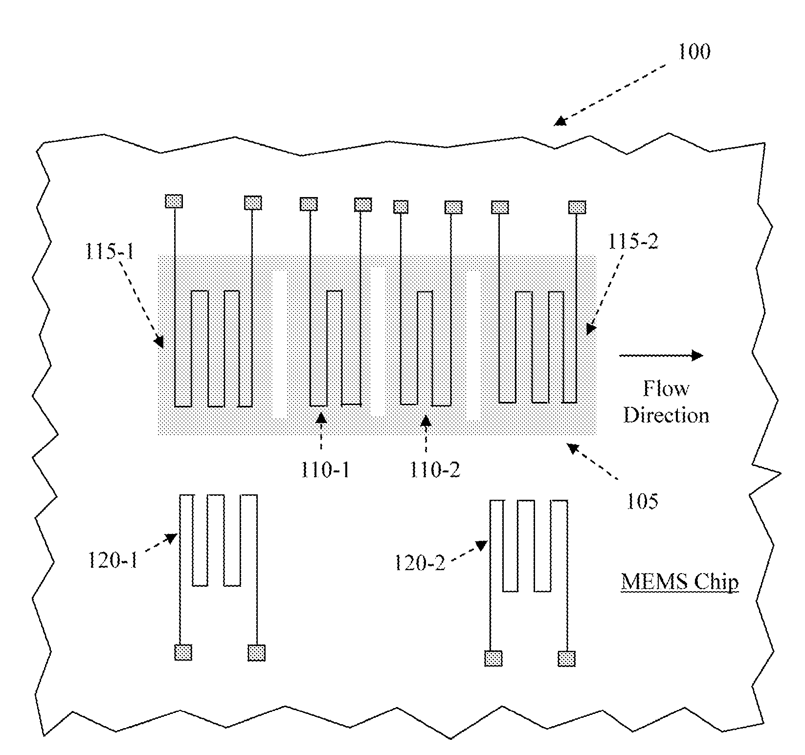
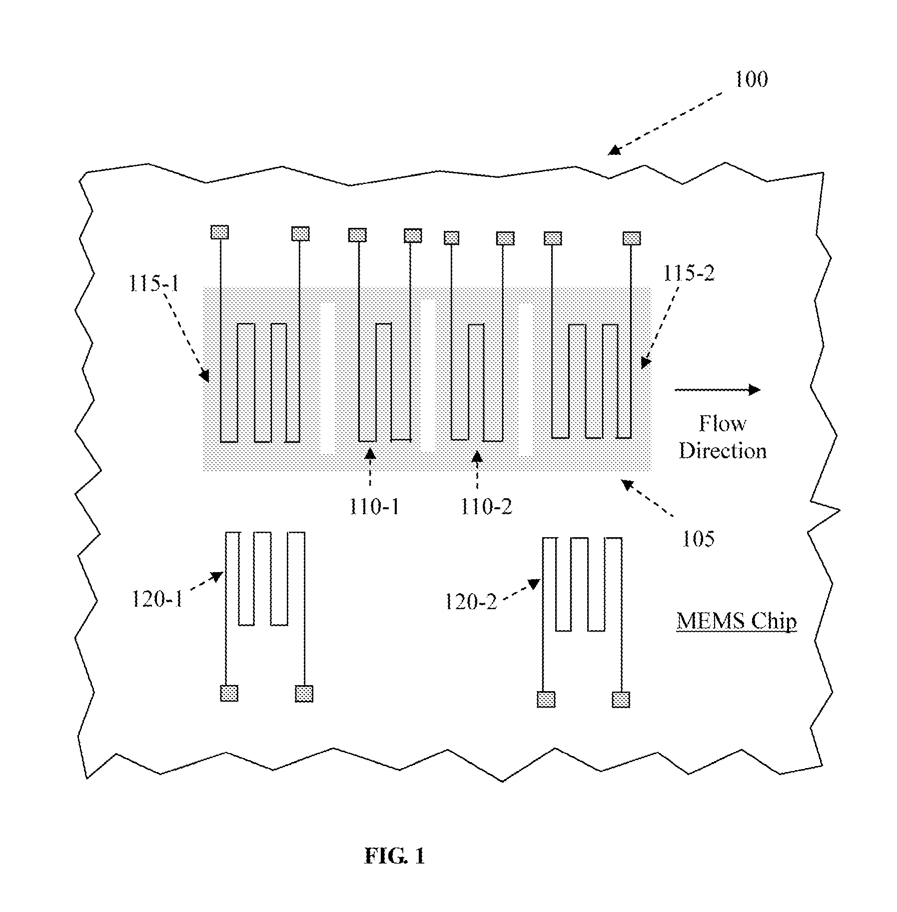
[0023]FIG. 1 shows a top view of a flow rate sensor 100 as a preferred embodiment of the present sensor. The flow rate sensor 100 is supported on a membrane 105 and is manufactured by applying the MEMS manufacturing processes as illustrated below. The flow rate sensor includes an upstream heater 110-1 and a downstream heater 110-2 as well as two temperature sensing resistors 115-1 and 115-2 disposed on the upstream and downstream respectively of the heaters 110-1 and 110-2. Each of the heaters 110-1 and 110-2 is a thin-film heating element and the temperature sensing resistors 115-1 and 115-2 is a pair of thin-film sensing resistors on a thin thermally isolated membrane 105 disposed over a micro-machined silicon substrate. The upstream and downstream sensing resistors 115-1 and 115-2 respectively may be symmetrical, i.e., resistors of equal resistance, or non-symmetrical resistors, i.e., resistors of different resistances. The upstream and downstream sensing resistors may be arrange...


PUM


Abstract

An integrated mass flow sensor is manufactured by a process of carrying out a micro-machining process on an N or P-type silicon substrate with orientation <100>. This mass flow sensor comprises an upstream thin-film heater, an downstream thin-film heater, and a pair of thin-film heat sensing elements, and a thermally isolated membrane for supporting the heaters and the sensors out of contact with the substrate base. This mass flow sensor is operated with three sets of circuits, a first circuit for measuring a flow rate in a first range of flow rates, a second circuit for measuring a flow rate in a second range of flow rates, and a third circuit in a differential configuration for measuring a flow rate in said first range of flow rates or said second range of flow rates, to significantly increase range of flow rate measurements and provide an optional for concentration measurement, while maintains a high degree of measurement accuracy.

Description

BACKGROUND OF THE INVENTION[0001]1. Field of the Invention[0002]The present invention generally concerns thermal mass flow sensors, and more particularly, concerns thermal mass flow sensors made of micro-electro-mechanical systems (MEMS) approach, and methods of manufacturing and operating such mass flow sensors.[0003]2. Description of the Related Art[0004]Heat transfer principle has been widely used for mass flow measurements. Thermal mass flow sensors can be found in many applications in industrial process monitor and control, medical gas flow management, and environmental equipments, to name a few. One of the major concerns on the traditional mass flow sensors is the large power consumption used to heating the fluid flow that leads to an uncertainty in low flow measurement domain and restrains on some applications such as gas trade metrology. The difficulties of making identical sensors also make manufacture cost higher than those for other technology. MEMS technology, on the con...

Claims


Application Information

Patent Timeline
Patent Type & Authority Applications(United States)
IPC IPC(8): G01F25/00G01F1/69
CPCG01F1/6845G01F1/698G01F1/6965G01F1/692
Inventor WANG, GAOFENGCHEN, CHIH-CHANGYAO, YAHONGHUANG, LIJI
Owner M TECH INSTR HLDG
Why Eureka
Try Eureka