Method and apparatus for testing leakage of pipe passage

Inactive Publication Date: 2009-07-02
FUJIKIN INC +1
View PDF2 Cites 18 Cited by
  • Summary
  • Abstract
  • Description
  • Claims
  • Application Information

AI Technical Summary

Benefits of technology

[0020]The present invention is constituted so that, first, the internal capacity of a pipe passage undergoing testing is computed using a computation treatment device by using a flow rate detecting signal Q from a flow rate measuring device, a pressure detecting signal P2 from a pressure detector and a temperature detecting signal T from a temperature detector, and the leaked volume of the pipe passage is computed using the computed internal capacity and the pressure drop value of the pipe passage detected after a lapse of a given time. As a result of the present invention, the structure of the computation treatment device can be substantially simplified compared with conventional leakage testing methods of this type, and the internal cap

Problems solved by technology

However, there are some disadvantages found with using the pressurizing method.
They are that (a) a long testing time is required, (b) it is not easy to spot the precise location of leakage, (c) an exact internal capacity of a pipe passage undergoing testing has to be obtained to determine the degree of leakage from the leakage test results because pressure drop velocity changes largely depending on the internal capacity of the pipe passage undergoing testing, and the like.
Therefore, it is practically impossible that the internal capacities of pipe passages are obtained with accuracy on a piping chart.
So, when actual leakage testing of a pipe passage is performed, the leaked volume (Pa·m3/sec) associated with internal capacity of the pipe passage cannot be employed as a base to determine the degree of leakage from leakage testing of the pipe passage.
However, even with these pressurizing method techniques, there still rema

Method used


Image

  • Method and apparatus for testing leakage of pipe passage
  • Method and apparatus for testing leakage of pipe passage
  • Method and apparatus for testing leakage of pipe passage

Examples


embodiment 1

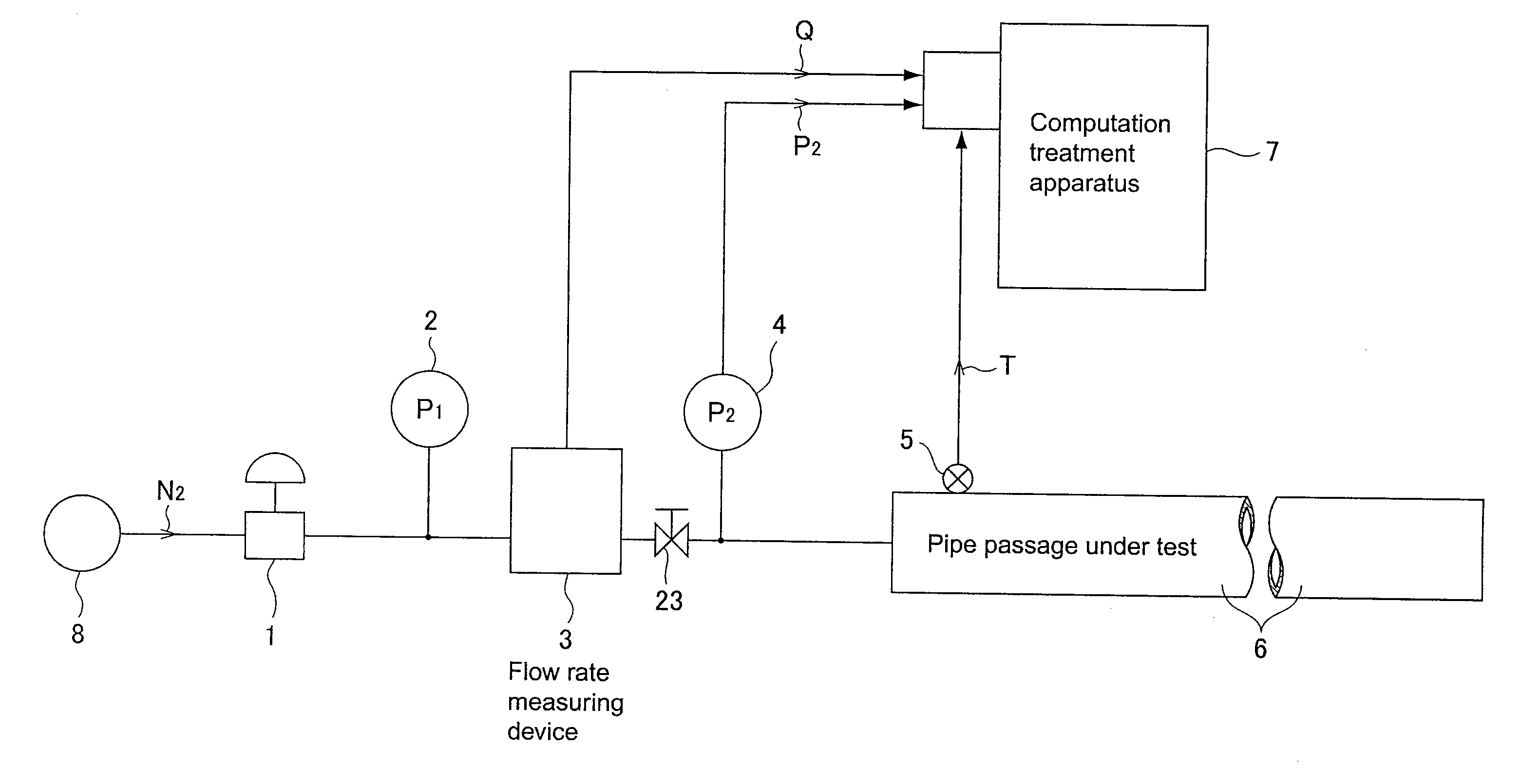
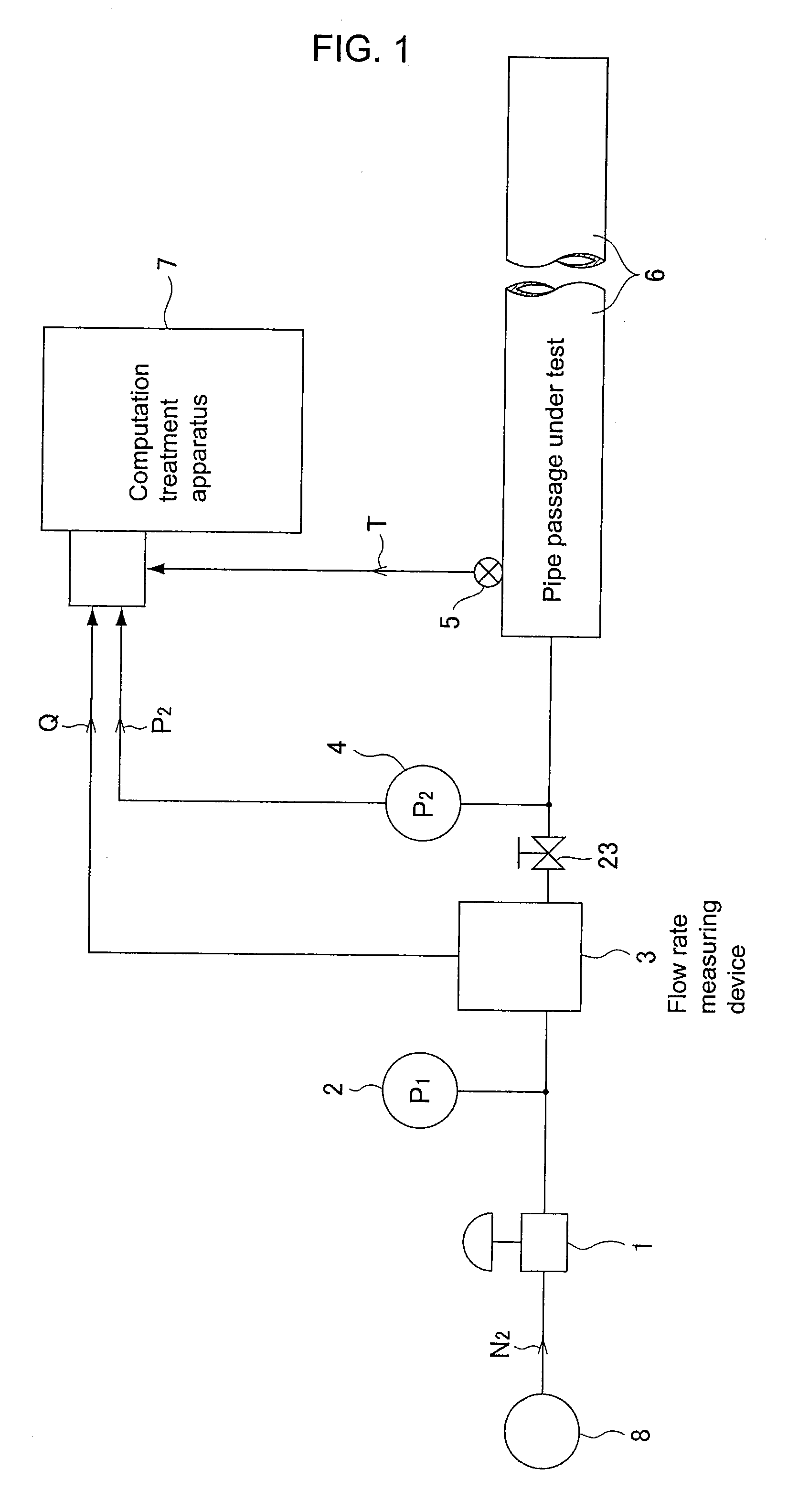
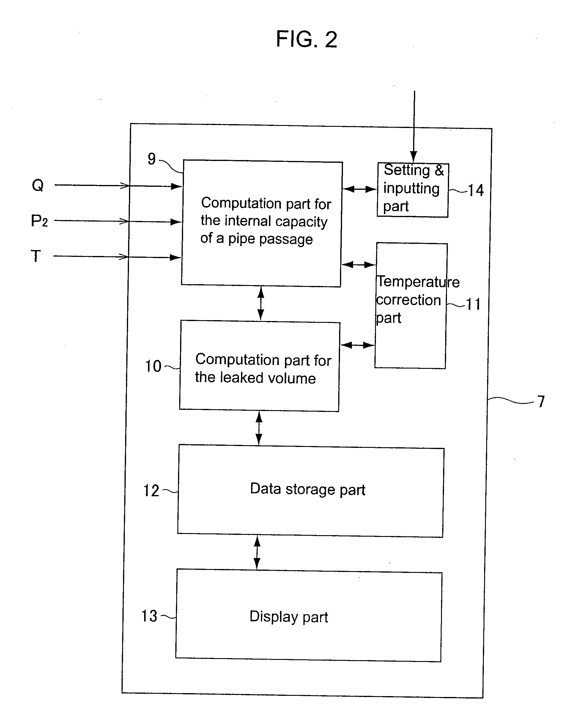
[0090]FIG. 5 is a schematic diagram illustrating an embodiment of the method for testing leakage in accordance with the present invention. In FIG. 5, 1 designates a pressure adjustor, 2 and 18 designate pressure detectors (pressure transducers), 3 designates a flow rate measuring device, in this case a thermal type mass flow meter (a mass flow controller flow rate·N2 100 sccm), 5 designates a temperature detector (a thermostat), 6 designates a pipe passage undergoing testing, 7 designates a computation treatment apparatus (a data logger), 8 designates a N2 gas source, V1 and V2 designate metal diaphragm valves, 19 designates a leak sample (approx. 10−6˜10−5 Pa·m3), 20 designates a blind, 21 designates a stainless steel pipe of outer diameter 6.35 mm and inner diameter 4.35 mm, and 22 designates a stainless steel pipe of outer diameter 9.52 mm and inner diameter 7.52 mm.

[0091]First, in step (a), a flow rate setting is made for the flow rate measuring device (MFC) 3 in order that the ...


PUM


Abstract

A method for testing leakage of a pipe passage employs a flow rate of gas used in testing supplied to the inside of a pipe passage undergoing testing hermetically sealed on one side while detecting flow rate with a flow measuring device and pressure with a pressure detector, and detecting temperature of the gas used, and inputting the detected values of pressure, flow rate and temperature into a computation treatment apparatus, and internal capacity VL of the pipe passage is computed as VL=(supplied flow rate Q×pressure applied time Δt)/(pressure rise value ΔP2), and next, the volume QL leaked from the pipe passage is computed as QL=(pressure drop value ΔP2′×internal capacity VL)/(pressure drop time Δt′).

Description

[0001]This is a National Phase Application in the United States of International Patent Application No. PCT / JP2007 / 000161 filed Mar. 2, 2007, which claims priority on Japanese Patent Application No. 2006-057327, filed Mar. 3, 2006. The entire disclosures of the above patent applications are hereby incorporated by reference.FIELD OF THE INVENTION[0002]The present invention is to be used, for example, in semiconductor manufacturing facilities, chemical products manufacturing facilities and the like, and relates to a method for testing leakage of various types of gases from supply pipe passages and to a leak testing apparatus to be used for the same.BACKGROUND OF THE INVENTION[0003]Many gas supply apparatuses have been employed in semiconductor manufacturing facilities, and the like, and gas supply pipe passages including flow control valves, flow measuring devices, and the like, are under strict control to prevent gas leakage.[0004]With regard to techniques for testing leakage of gas ...

Claims


Application Information

Patent Timeline
IPC IPC(8): G01M3/08
CPCG01M3/2815G01B13/24G05D7/00G01N3/12G01N2203/023
Inventor KOHNO, GISUKEHON'IDEN, TERUOMORIMOTO, AKIHIROYASUMOTO, NAOFUMIKAWADA, KOJIUEJI, YUTAKAIKEDA, NOBUKAZUHATANO, MASAYUKIKURAMOCHI, MICHIOKINDAI, YOSHIYUKINAGANO, KAZUHIROWADA, TOSHIAKI
Owner FUJIKIN INC
Why Eureka
Try Eureka