Thermal Electric Power Generation System, Heating Medium Supply System, and Temperature Fluctuation Suppressing Device

a technology of thermal electric power generation and heating medium, which is applied in the direction of steam engine plants, steam engine parts, machines/engines, etc., can solve the problems of electric power generation that cannot be continued all day long, the system investment cost is limited, and the problem of unavoidable problems, so as to reduce the risk of electric power generation failure, and reduce the effect of short-cycle and medium-cycle temperature fluctuations

Inactive Publication Date: 2009-07-02
KAWASAKI HEAVY IND LTD
View PDF9 Cites 17 Cited by
  • Summary
  • Abstract
  • Description
  • Claims
  • Application Information

AI Technical Summary

Benefits of technology

[0123]According to the present invention, a liquid heating medium which is supplied to a heat exchanging device in such a system as a solar thermal electric power generation system while fluctuating in temperature is subjected to time-lag mixing relying upon a simple arrangement, whereby the tempe...

Problems solved by technology

Actually, however, limitations on the system investment cost and running cost limit the heat storage capacity to about 4 to 6 hours in terms of electric power generating duration and, therefore, electric power generation cannot be continued all day long.
Regardless of whether the conventional solar thermal electric power generation system or the integrated solar combined cycle electric power generation system is used, there exists an unavoidable problem.
This problem is associated with the condition of solar radiation onto the surface of the Earth incidentally changing (with time) during daytime.
As a result, the condition of generated steam (including temperature, pressure, dryness and the like) to be supplied to the steam turbine always fluctuates, which causes the generated electricity to fluctuate.
If vigorous fluctuation occurs in the condition of steam, the waste heat recovery boiler or the steam turbine might be damaged thereby.
With the two systems disclosed in patent documents 1 and 2 for example,...

Method used


Image

  • Thermal Electric Power Generation System, Heating Medium Supply System, and Temperature Fluctuation Suppressing Device
  • Thermal Electric Power Generation System, Heating Medium Supply System, and Temperature Fluctuation Suppressing Device
  • Thermal Electric Power Generation System, Heating Medium Supply System, and Temperature Fluctuation Suppressing Device

Examples


Embodiment Construction

[0225]Embodiments of integrated solar combined cycle electric power generation system, heating medium supply system and temperature fluctuation suppressing device according to the present invention will be described with reference to the attached drawings.

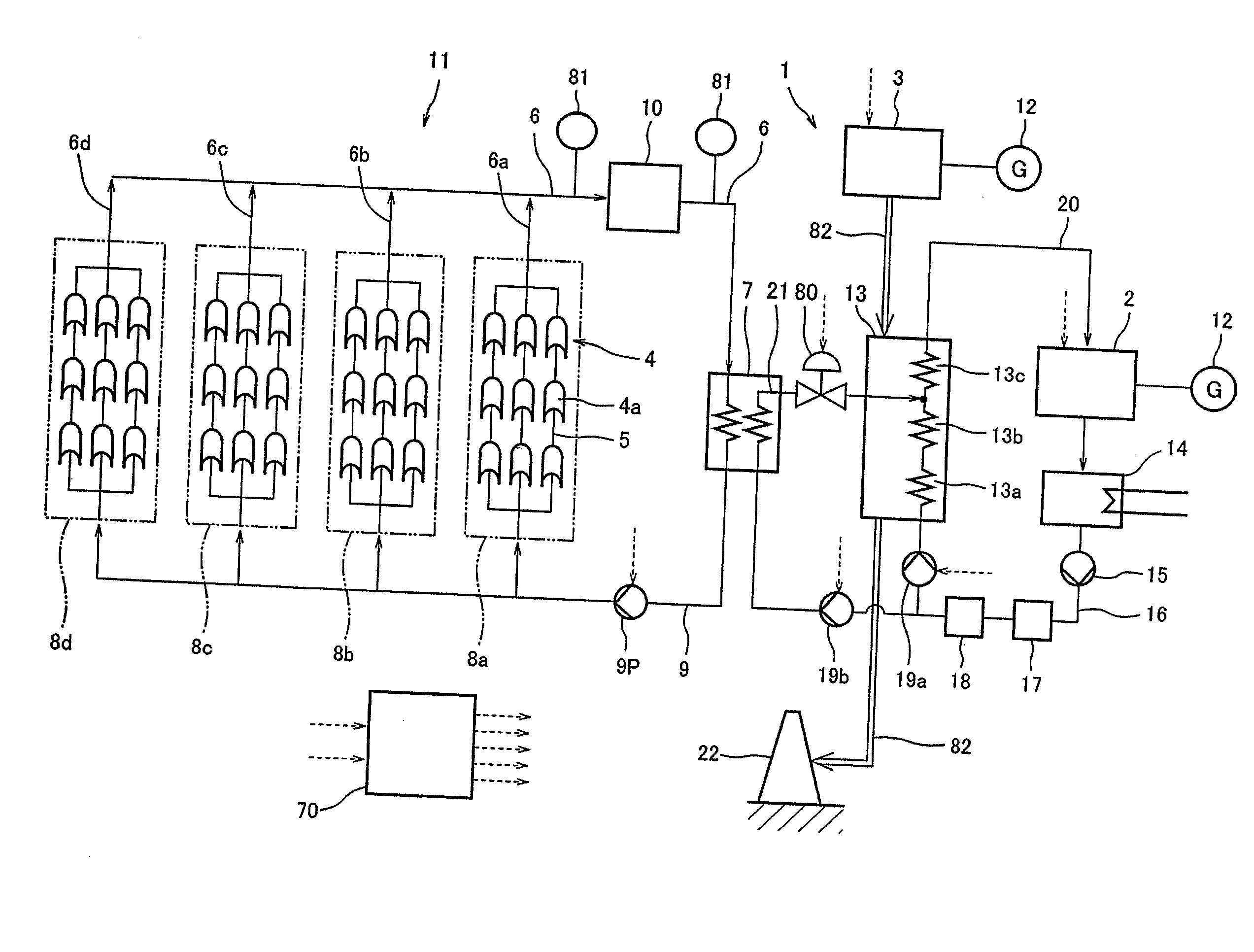
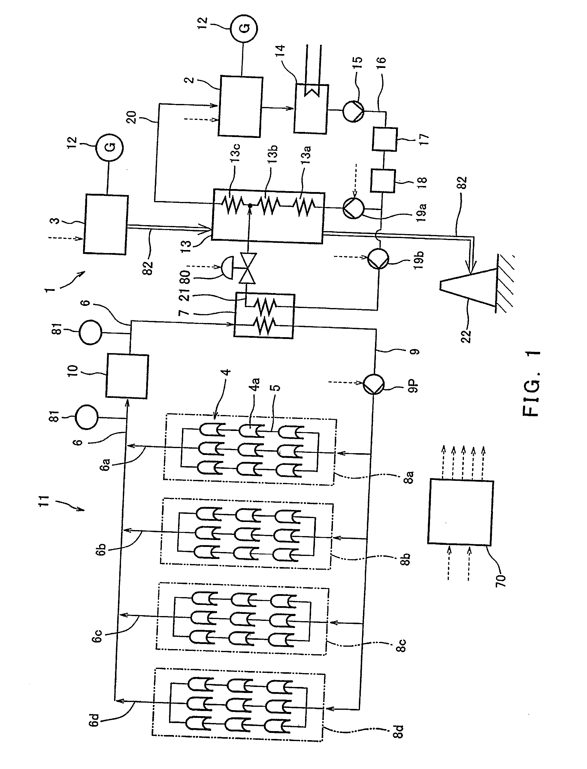
[0226]FIG. 1 shows an integrated solar combined cycle electric power generation system 1 in which steam turbine electric power generation by a steam turbine 2 driven by utilizing part of the steam generated while relying upon solar heat and gas turbine electric power generation by a gas turbine 2 driven by burning a fuel gas such as natural gas are combined with each other. The electric power generation system 1 uses reflectors 4a of the parabolic trough type forming a heat collecting unit 4. Each of the reflectors 4a is trough-shaped having a parabolic section in an X-Y plane and configured to reflect rays of sunlight incident thereon to collect them on its focal point.

[0227]A heat absorbing tube 5, which extends through the focal...


PUM


Abstract

A temperature fluctuation suppressing device for a heating medium is provided which is capable of sufficiently suppressing temperature fluctuations of the heating medium at the time of supplying collected solar heat for steam generation. The temperature fluctuation suppressing device includes a heating medium mixer provided on a heating medium supply passage configured to supply a liquid heating medium to a heat exchanging device, the heating medium mixer including: a heating medium passage forming member having plural heating medium passages; an inlet member and an outlet member provided separately from the inlet member, whereby the heating medium continuously flowing into the heating medium passage forming member through the inlet member passes through the plural heating medium passages with time-lags to form respective streams, which are then joined together before flowing out through the outlet member.

Description

TECHNICAL FIELD[0001]The present invention relates to a solar thermal electric power generation system, a heating medium supply system, and a temperature fluctuation suppressing device. More specifically, the present invention relates to: a solar thermal electric power generation system configured to generate steam by means of a heating medium heated by solar heat and drive a steam turbine by means of steam thus generated to generate electricity; a heating medium supply system configured to supply the heating medium heated by solar radiation; and a temperature fluctuation suppressing device for suppressing temperature fluctuation of the heating medium.BACKGROUND ART[0002]A conventional solar thermal electric power generation system 101 shown in FIG. 25 has a configuration wherein: sunlight is collected by means of a concentrating type heat collecting unit (hereinafter will be referred to as “heat collecting unit” simply) 102; a heating medium absorbs collected sunlight as thermal en...

Claims


Application Information

Patent Timeline
IPC IPC(8): F24J2/04F24S10/70F24S90/00
CPCF03G6/00F03G6/064F03G6/067F22B37/227F24J2/07F24J2002/4603F24J2/42F24J2/4649F28F9/0278F28F13/06Y02E10/46F24J2/14F24S80/20F24S23/74F24S90/00F24S20/20F24S2080/05
Inventor OTA, HIDEAKI
Owner KAWASAKI HEAVY IND LTD
Why Eureka
Try Eureka