Casting method and apparatus

a casting method and apparatus technology, applied in the field of casting technologies, can solve the problems of reducing the yield of products, dendritic growth tending to break down, and misoriented grains are likely to form, and achieve the effect of eliminating the formation of macrosegregation defects such as freckles and high quality

Inactive Publication Date: 2009-07-02
EBISU
View PDF9 Cites 8 Cited by
  • Summary
  • Abstract
  • Description
  • Claims
  • Application Information

AI Technical Summary

Benefits of technology

[0012]This invention is concerned with unidirectional solidification process and remelting processes such as ESR and VAR, and provides with casting technologies for producing high quality castings and ingots without such macrosegregation defects as freckles caused primarily by the liquid flow within the mushy zone during solidification. With special attention paid to the above-mentioned liquid flow phenomena within the mushy zone, this invention has clarified for the first time that the interdendritic fluid flow with extremely low velocity can be suppressed by exerting high magnetic field onto the whole mushy zone, and thereby the formation of the macrosegregation defects such as freckles can be eliminated.

Problems solved by technology

However, casting defects such as channel segregation (so called freckles), misoriented grains, microporosity tend to occur in these blades, thus lowering the yield of the products (for example, refer to p.
Also, dendritic growth tends to break down and misoriented grains are likely to form.
Despite that a vast amount of efforts have been paid to improve these casting defects by optimizing casting parameters such as sustaining temperature in the radiation heating zone, withdrawal rate, radiation cooling rate, etc. or by adjusting alloy compositions so as to add heavier elements than Ni (for example Ta), it still remains insufficient.
(2)), and that these macrosegregation defects can occur in the alloys of ‘downward type of buoyancy’ where interdendritic liquid density increases as solidification proceeds, as well as in the aforementioned alloys of ‘upward type’ of buoyancy.
However, as the cross-section of the ingots become larger, the formation of these macrosegregation defects is unavoidable.

Method used


Image

  • Casting method and apparatus
  • Casting method and apparatus
  • Casting method and apparatus

Examples


example 1

A. Specific Example 1

Macrosegregation in Unidirectional Solidification of Ni-10 wt % Al Round Ingot

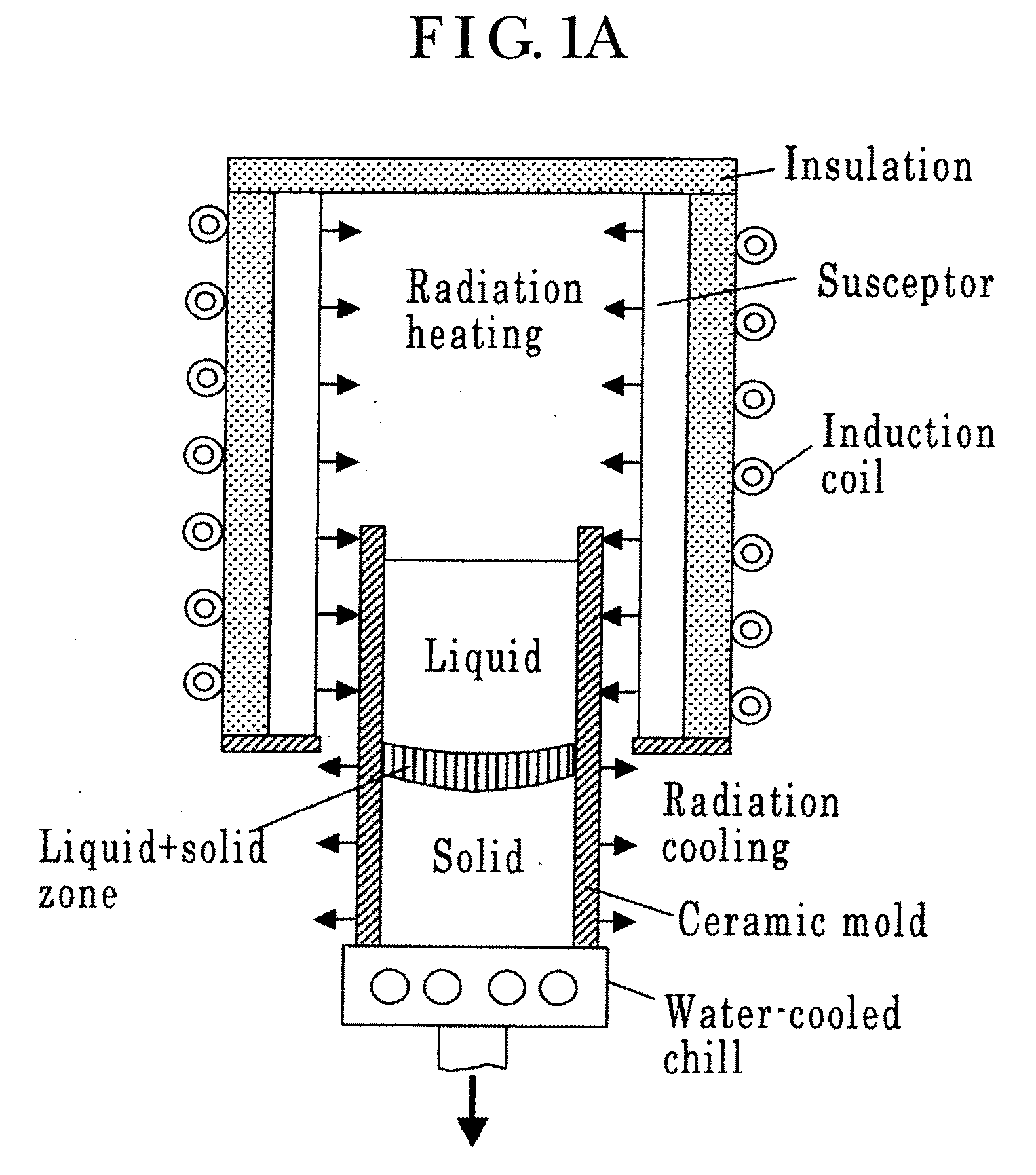
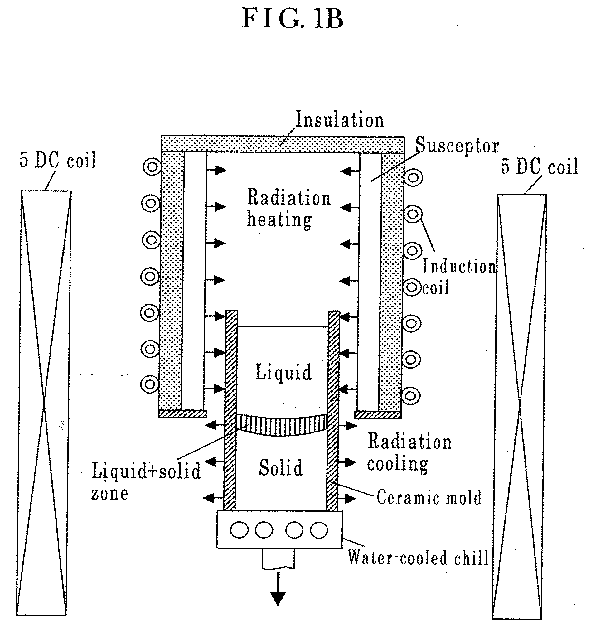
[0089]Schematic diagram of a conventional unidirectional solidification apparatus is shown in FIG. 1(A). Susceptor is heated by induction coil and the ceramic mold is then radiation-heated by the susceptor. The bottom of the ceramic mold is cooled by water-cooled chill, and the mold is withdrawn gradually downward to establish unidirectional solidification (instead, it is also possible to rise the heating furnace while the mold is fixed). Giamei and Kear have shown that the channel segregation generally termed ‘freckles’ appears at O.D. of unidirectionally solidified Ni-base superalloy monocrystal round ingots of the type upward buoyancy (refer to FIGS. 1 to 4 of Ref. (6)), and clarified the size effect that more freckles form as the diameters of the ingots increase (refer to Table II of the same reference). They have also shown that the freckles take place at O.D. of unidirectionally ...

example 2

B. Specific Example 2

Macrosegregation of Unidirectionally Solidified Ni-10 wt % Al Square Ingot

[0096]In order to investigate the influences of magnetic field directions on the formation of freckles, calculations were done for square ingots. The dimensions of cross section were determined to have the equivalent cross-sectional area to that of the Specific Example 1, i.e., 60 mm square. All other casting parameters are the same as those of round ingot (refer to Table 2). Computations were performed for ¼ cross-sections considering the symmetricity. The number of elements for the ingot is 23004 (18 in X dir.×18 in Y dir.×71 in Z dir.).

[0097]The macrosegregations of the conventional ingot with no magnetic field are shown in FIGS. 9 to 11. As shown in FIGS. 9(A) and 9(B), the freckles take place in vertical sections at outsides with roughly equal intervals. The maximum value of C / Co is about 1.18. FIGS. 10(A) and 10(B) show the states of macrosegregation being formed after 20 minutes dur...

example 4

D. Specific Example 4

Macrosegregation of Remelting-Processed IN718 Ni-Base

[0108]Superalloy Ingot

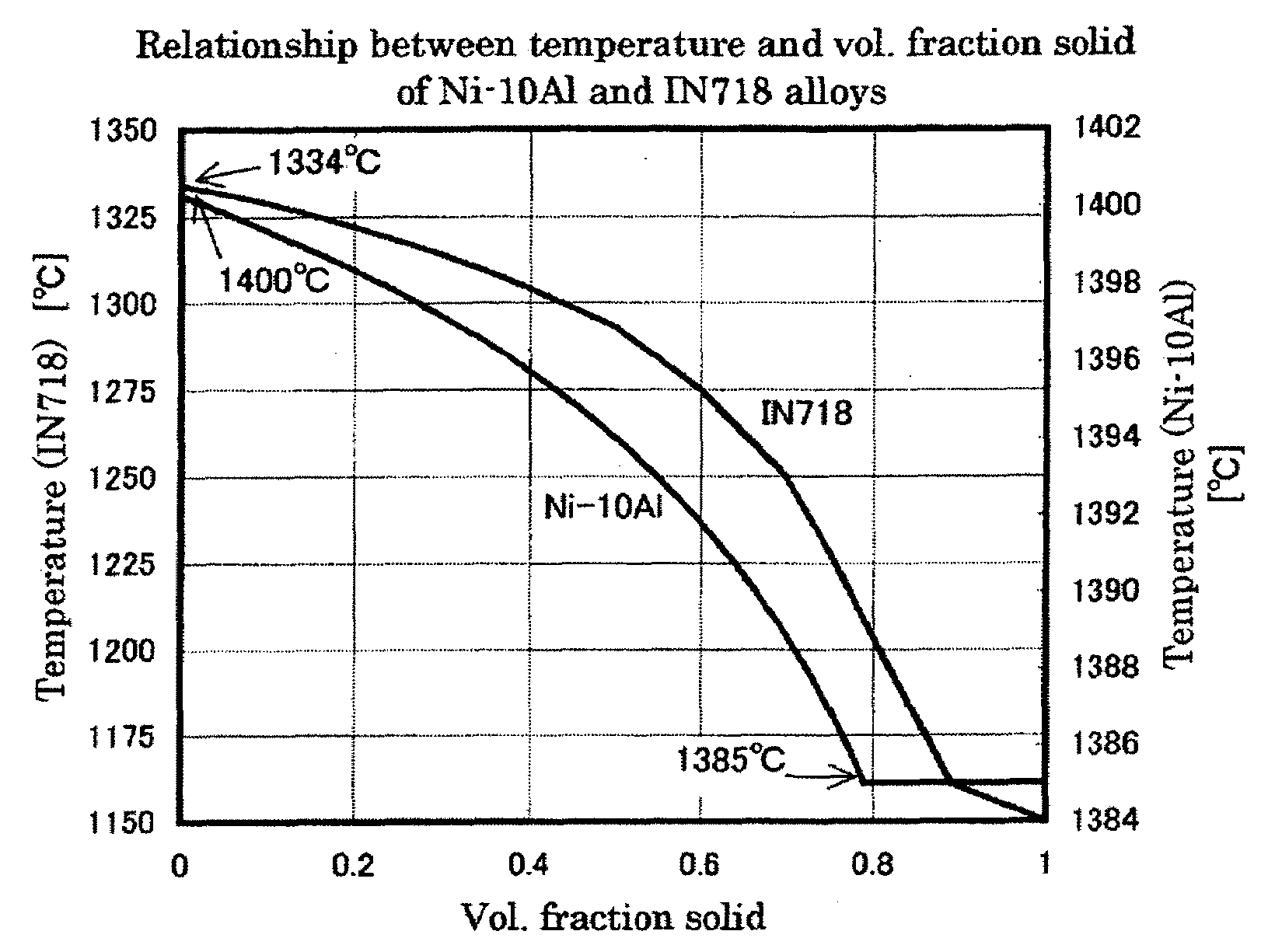
[0109]The chemical compositions and physical properties used for computations are given in Table 3. The chemical compositions and the relationships between temperature vs. liquidus compositions and temperature vs. solidus compositions respectively in the multi-component system of IN718 were reproduced from FIGS. 1 to 3 of Ref. (10). Hence, the computational results of the relationship between temperature and vol. fraction solid (refer to FIG. 2), and the variations of solute concentrations in liquid phase during solidification (refer to FIG. 4) are the same as those of Ref. (10). Also, the variation of the liquid density by Eq. (8) is shown in FIG. 5, indicating that the alloy is of downward type of buoyancy.

[0110]Van Den Avyle, et al. reported in the aforementioned Ref. (2) that freckles formed in the middle of radial direction and ‘central’ freckles formed at the center in remelting-pro...


PUM

PropertyMeasurementUnit
static magnetic fieldaaaaaaaaaa
magnetic fieldaaaaaaaaaa
static magnetic fieldaaaaaaaaaa

Abstract

This invention is concerned with the productions of unidirectionally solidified castings and remelting-processed ingots such as ESR or VAR, which has paid special attention to the liquid flow phenomena within solid-liquid coexisting phase (mushy phase) during solidification, and made it clear for the first time that by applying high static magnetic field onto the whole mushy phase, the extremely slow interdendritic liquid flow responsible for the formation of macrosegregation can be suppressed, and thereby that the macrosegregation such as freckles can completely be eliminated. Thus, this invention provides with a novel casting technology for producing high quality castings and ingots without macrosegregation.

Description

CROSS REFERENCE TO RELATED APPLICATIONS[0001]This is a Continuation Application of PCT Application No. PCT / JP2007 / 059353, filed Apr. 24, 2007, which was published under PCT Article 21(2) in English.[0002]This application is based upon and claims the benefit of priority from prior International Application No. PCT / JP2006 / 309133, filed Apr. 25, 2006, the entire contents of which are incorporated herein by reference.BACKGROUND OF THE INVENTION[0003]1. Field of the Invention[0004]This invention is concerned with the casting technologies for primarily improving macrosegregation defects in unidirectionally solidified castings which possess columnar dendrite structure consisting of polycrystalline grains (so called DS material) or dendrite structure consisting of a single crystalline grain (so called Monocrystal or SX material), and in the remelting-processed ingots such as Electroslag Remelting (ESR) and Vacuum Arc Remelting (VAR).[0005]2. Description of the Related Art[0006]A. Unidirecti...

Claims


Application Information

Patent Timeline
Patent Type & Authority Applications(United States)
IPC IPC(8): B22D27/02
CPCB22D11/11B22D11/115C22B9/003C22F3/02C22B9/20C30B28/06C30B29/52C22B9/18Y02P10/25
Inventor EBISU, YOSHIO
Owner EBISU
Why Eureka
Try Eureka