Drift tube structure for ion mobility spectrometer

a technology of ion mobility spectrometer and tube structure, which is applied in the field of safety inspection technology, can solve the problems of complex structure, complex structure, and inability to accurately measure the ion intensity, and achieve the effects of reducing the input capacitance of the front circuitry, less circuit noise, and dramatic increase of ion transmittan

Active Publication Date: 2009-07-02
NUCTECH CO LTD
View PDF9 Cites 10 Cited by
  • Summary
  • Abstract
  • Description
  • Claims
  • Application Information

AI Technical Summary

Benefits of technology

[0017]With the above structure of the present invention, an electric field having a periphery of uniform focusing center can be formed in the migration zone. The circular ring configuration of the electric field periphery can shield the migration electric field from any influence of external electric fields. The electrodes are each mesh-like and have a circular hole at the center, thus they can focus and collect as many as possible ions that do not move along the central axis, and those ions moving along the central axis can pass through the electrodes transparently. The electrodes close to the Faraday plate have smaller center holes. This configuration allows the pass-through of focused ion beams on one hand, and, on the other hand, can shield the Faraday plate from any influence of previous ion movement at these electrodes, thereby dramatically increasing ion transmittance. Since the ion beam is very thin, the Faraday plate can be made very small. This leads to reduced input capacitance of the front circuitry and less circuit noise.

Problems solved by technology

Unfortunately, a considerable quantity of ions may be scattered to the electrodes and disappear.
This technique has the disadvantage of complex structure and control.
Again, this method results in complex structure.
The internal electric field of the drift tube is susceptible to interference, and the peripheral ions are often scattered and disappear due to the electric field having a non-uniform edge.

Method used


Image

  • Drift tube structure for ion mobility spectrometer
  • Drift tube structure for ion mobility spectrometer
  • Drift tube structure for ion mobility spectrometer

Examples


Embodiment Construction

[0025]Now, preferred embodiments of the present invention will be described with reference to the figures, in which the same reference symbol, though shown in different figures, denotes the same or like component. For the purpose of clarity and simplicity, detailed description of known functions and structures incorporated here will be omitted, otherwise it may obscure the subject matter of the present invention.

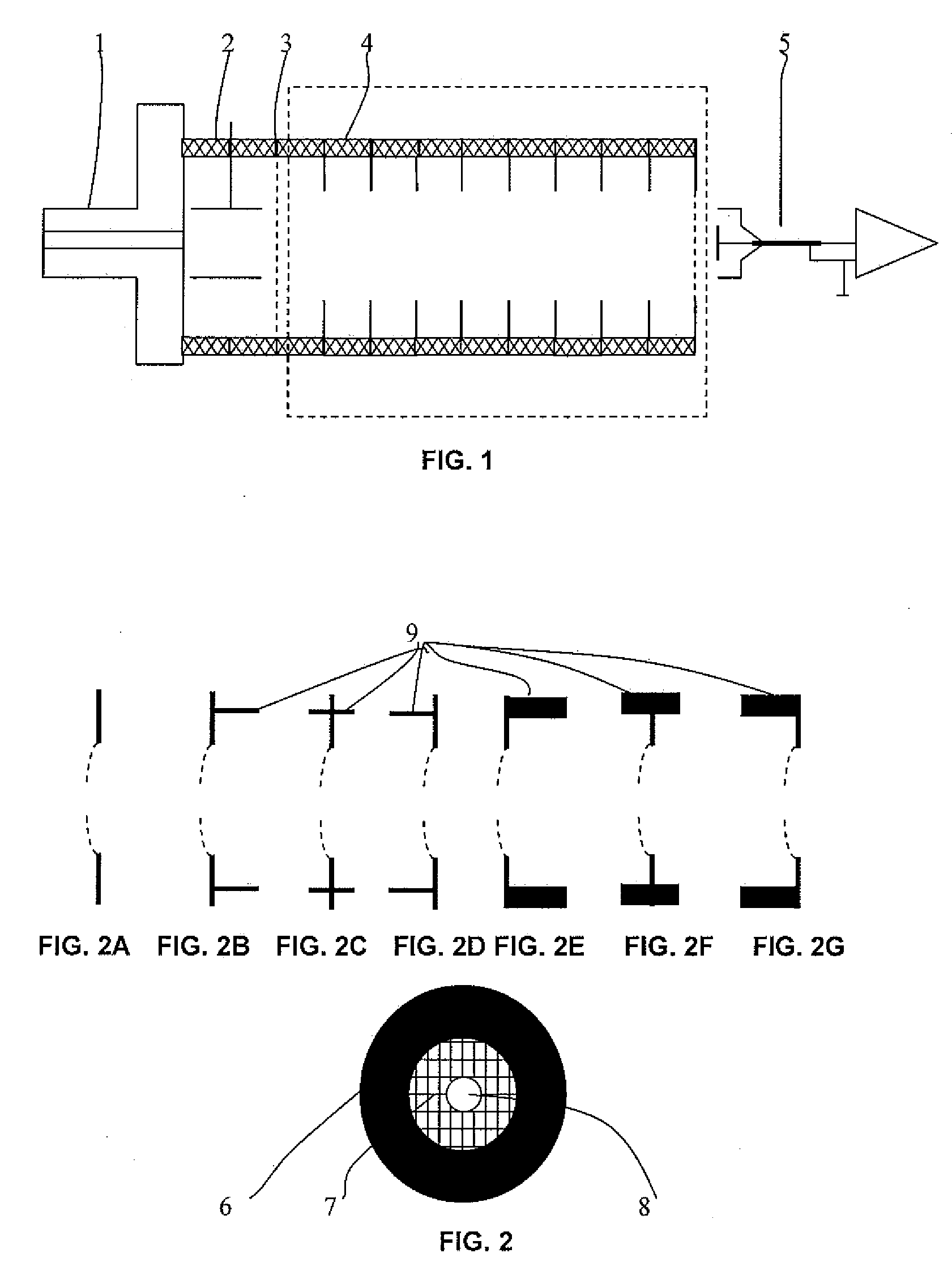
[0026]Referring to FIG. 2, the electrodes used in the drift tube of the present embodiment are each a mesh metal sheet having a radian or taper portion including the mesh radian or taper portion 7 of the electrode sheet, for example. The portion 7 is convexly curved toward an ion input. The death zone has very thin metal threads. The center 8 of the electrode sheet is a circular hole or a hole of any other shape. The periphery 6 of the electrode sheet is a metal configuration 9 having metal circular rings or rings of any other shape, such as square can, on one or both sides....


PUM


Abstract

A drift tube structure for ion mobility spectrometer is disclosed comprising electrode sheets and insulation parts arranged in alternation, with each electrode sheet being a mesh metal sheet having a radian or taper portion which is convexly curved toward an ion input. Further, the radian or taper portion of the electrode sheet has meshes of higher transparency. With the above structure of the present invention, an electric field having a periphery of uniform focusing center can be formed in the migration zone. The circular ring configuration of the electric field periphery can shield the migration electric field from any influence of external electric fields. The electrodes are each meshlike and have a circular hole at the center, thus they can focus and collect as many as possible ions that do not move along the central axis, and those ions moving along the central axis can pass through the electrodes transparently.

Description

CROSS REFERENCE TO RELATED APPLICATIONS[0001]This application claims priority under 35 U.S.C. Section 119 to Chinese application 200710308546.3, filed on Dec. 29, 2007. This application is hereby incorporated by reference in its entirety.BACKGROUND OF THE INVENTION[0002]1. Field of Invention[0003]The present invention relates to the field of safety inspection technology, in particular to a drift tube structure used in inspection equipment for inspecting drugs and explosives by means of ion mobility technique.[0004]2. Description of Prior Art[0005]Ion mobility spectrometer discriminates different ions according to a fact that different ions have different drift velocities in a uniform weak electric field. The ion mobility spectrometer is usually formed of a sample input section, an ionization section, an ion gate or an ion storage section, a migration zone, a collection zone, a sensing circuit, a data acquisition and processing and control section, etc.[0006]In the existing technique...

Claims


Application Information

Patent Timeline
Patent Type & Authority Applications(United States)
IPC IPC(8): H01J49/00
CPCG01N27/622
Inventor HU, HAIFENGLI, YUANJINGZHANG, QINGJUNCHEN, ZHIQIANG
Owner NUCTECH CO LTD
Why Eureka
Try Eureka