Wire bonding of aluminum-free metallization layers by surface conditioning

a technology of surface conditioning and bonding, applied in the field of integrated circuit formation, can solve the problems of increasing production costs and appropriately discharging any process, and achieve the effects of reducing contact failures, reliable assessment of processes and materials, and high degree of similarity in device areas

Inactive Publication Date: 2009-07-02
GLOBALFOUNDRIES INC
View PDF11 Cites 37 Cited by
  • Summary
  • Abstract
  • Description
  • Claims
  • Application Information

AI Technical Summary

Benefits of technology

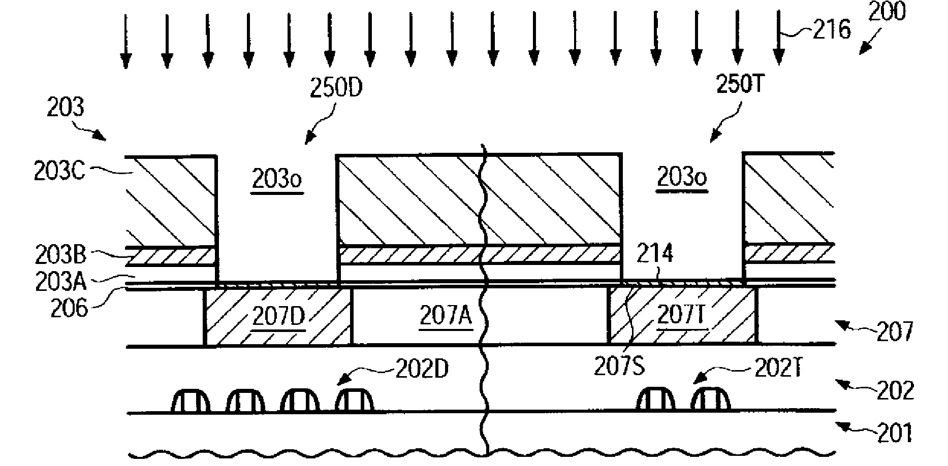
[0018]Generally, the subject matter disclosed herein relates to a technique and respective semiconductor devices in which wire bonding in copper-based metallization structures may be accomplished without using aluminum-based techniques by using appropriate metal for a contact area, such as copper, nickel and the like, which may also be used during the fabrication of the integrated circuit. Moreover, in order to reduce contact failures that may be caused by non-defined oxidation during the wire bonding process, the surface of the contact area may be provided with a continuous protection layer, for instance an oxide layer, which may passivate the respective metal surface, such as copper, nickel and the like, prior to the actual wire bonding process. In some illustrative aspects disclosed herein, the wire bonding may be advantageously combined with the concurrent formation of bump structures in other device areas, thereby providing a high degree of similarity in device areas including the bump structures and device areas including the wire bond structures, for instance with respect to the final passivation layer stacks. Thus, when forming test structures in advanced integrated circuits, which are connected on the basis of a wire bond contact structure, substantially the same overall device configuration may be obtained in the test structure, for instance with respect to the metallization structure, which may therefore enable a reliable assessment of processes and materials involved in the formation of the metallization structure. Furthermore, in addition to a high degree of process compatibility of test regions and actual device regions, resources in terms of equipment and clean room area may be freed compared to conventional strategies in which aluminum-based contact techniques are used or in which contact areas of wire bond structures may have to be coated with appropriate metals, such as gold, which may, in addition to increasing production costs, also cause further problems in appropriately discharging any process byproducts created during the electrochemical application of, for instance, gold onto respective contact areas.

Problems solved by technology

Furthermore, in addition to a high degree of process compatibility of test regions and actual device regions, resources in terms of equipment and clean room area may be freed compared to conventional strategies in which aluminum-based contact techniques are used or in which contact areas of wire bond structures may have to be coated with appropriate metals, such as gold, which may, in addition to increasing production costs, also cause further problems in appropriately discharging any process byproducts created during the electrochemical application of, for instance, gold onto respective contact areas.

Method used


Image

  • Wire bonding of aluminum-free metallization layers by surface conditioning
  • Wire bonding of aluminum-free metallization layers by surface conditioning
  • Wire bonding of aluminum-free metallization layers by surface conditioning

Examples


Embodiment Construction

[0031]Various illustrative embodiments of the invention are described below. In the interest of clarity, not all features of an actual implementation are described in this specification. It will of course be appreciated that in the development of any such actual embodiment, numerous implementation-specific decisions must be made to achieve the developers' specific goals, such as compliance with system-related and business-related constraints, which will vary from one implementation to another. Moreover, it will be appreciated that such a development effort might be complex and time-consuming, but would nevertheless be a routine undertaking for those of ordinary skill in the art having the benefit of this disclosure.

[0032]The present subject matter will now be described with reference to the attached figures. Various structures, systems and devices are schematically depicted in the drawings for purposes of explanation only and so as to not obscure the present disclosure with details ...


PUM


Abstract

In sophisticated semiconductor devices including copper-based metallization systems, a substantially aluminum-free bump structure in device regions and a substantially aluminum-free wire bond structure in test regions may be formed on the basis of a manufacturing process resulting in identical final dielectric layer stacks in these device areas. Moreover, reliable wire bond connections may be obtained by providing a protection layer, such as an oxide layer, after exposing the respective contact metal, such as copper, nickel and the like, thereby providing highly uniform process conditions during the subsequent wire bonding process. The number of process steps may be reduced by making a decision as to whether a substrate is to become a product substrate or test substrate for estimating the reliability of actual semiconductor devices. For example, nickel contact elements may be formed above copper-based contact areas wherein the nickel may provide a base for wire bonding or forming a bump material thereon.

Description

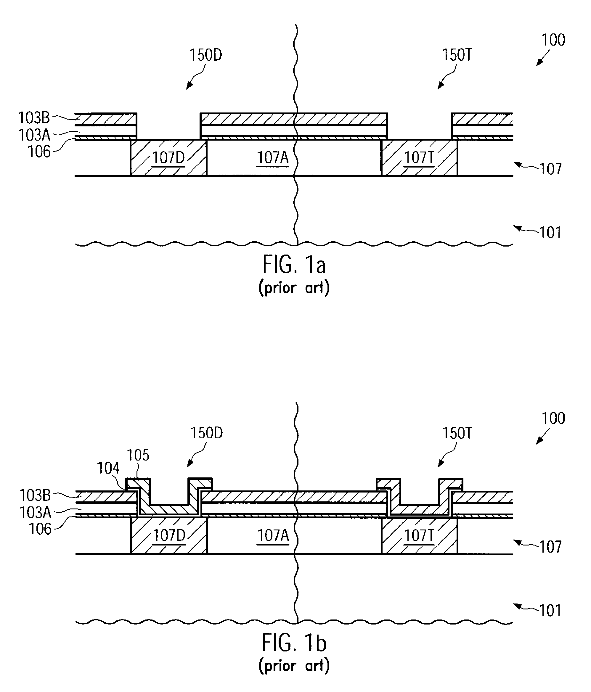
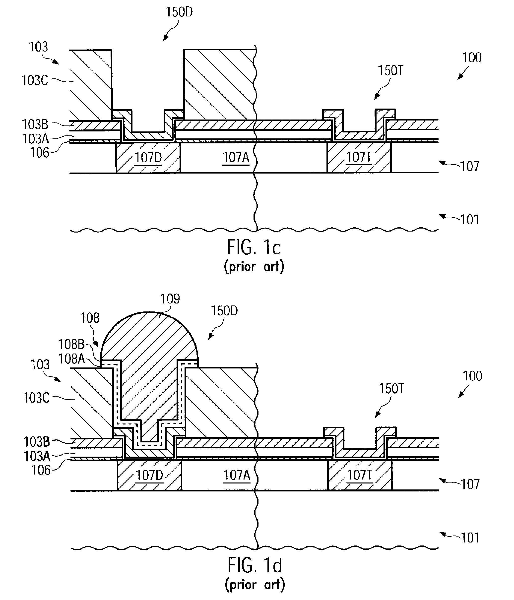
BACKGROUND OF THE INVENTION[0001]1. Field of the Invention[0002]The present disclosure generally relates to the formation of integrated circuits, and, more particularly, to a back end of line processing for a wire bonding structure in sophisticated metallization structures, for instance, located outside the die area of advanced integrated circuits, such as the frame region of semiconductor devices.[0003]2. Description of the Related Art[0004]In manufacturing integrated circuits, it is usually necessary to package a chip and provide leads and terminals for connecting the chip circuitry with the periphery. In some packaging techniques, chips, chip packages or other appropriate units may be connected by means of solder balls, formed from so-called solder bumps, that are formed on a corresponding layer of at least one of the units, for instance, on a dielectric passivation layer of the microelectronic chip. In order to connect the microelectronic chip with the corresponding carrier, the...

Claims


Application Information

Patent Timeline
Patent Type & Authority Applications(United States)
IPC IPC(8): H01L23/52H01L21/44
CPCH01L21/76888H01L24/05H01L24/45H01L24/48H01L24/85H01L2224/0347H01L2224/04042H01L2224/04073H01L2224/05082H01L2224/05147H01L2224/05155H01L2224/05166H01L2224/05647H01L2224/05655H01L2224/10126H01L2224/114H01L2224/1147H01L2224/116H01L2224/45124H01L2224/45144H01L2224/45147H01L2224/48463H01L2224/85009H01L2224/8501H01L2224/85205H01L2224/85375H01L2924/01005H01L2924/01007H01L2924/01013H01L2924/01014H01L2924/01022H01L2924/01028H01L2924/01029H01L2924/0105H01L2924/01073H01L2924/01074H01L2924/01078H01L2924/01079H01L2924/01082H01L2924/01327H01L2924/014H01L2924/04941H01L2924/04953H01L2924/05042H01L2924/14H01L2924/19043H01L2924/30105H01L2924/01006H01L2924/01019H01L2924/01033H01L2924/01068H01L2224/48647H01L2224/48655H01L2224/48847H01L2224/48855H01L2224/48747H01L2224/48755H01L2224/02166H01L2224/0401H01L2924/1306H01L2924/00014H01L2924/00H01L24/03H01L2224/03009H01L2224/03019H01L2224/451H01L2924/00015
Inventor LEHR, MATTHIASKUECHENMEISTER, FRANK
Owner GLOBALFOUNDRIES INC
Why Eureka
Try Eureka