AC-powered, microprocessor-based, dimming LED power supply

a technology of led power supply and microprocessor, which is applied in the direction of ignition automatic control, process and machine control, instruments, etc., can solve the problems of large input and/or output storage capacitance devices, high cost and space consumption, and undesirable use in many applications, so as to improve the audible noise level generated by the triac-dimming circuit, the effect of reducing the 120 hz audible nois

Active Publication Date: 2009-07-02
TEXAS INSTR INC
View PDF4 Cites 128 Cited by
  • Summary
  • Abstract
  • Description
  • Claims
  • Application Information

AI Technical Summary

Benefits of technology

[0011]In a second process, a proportional current limit adjustment is used to control the duty cycle. As a result, at relatively low phase angles, peak and average currents can be lowered, improving the audible noise levels generated by the circuit.
[0012]Advantageously, 120 Hz audible noise generated by the TRIAC-dimming circuit is reduced; dimming performance at low-light power levels can be enhanced without flicker; and non-linear dimming techniques can be implemented that, to the human eye, appears to be more “linear”.

Problems solved by technology

Relatively large input and / or output storage capacitative devices, however, are expensive and consume space, hence, their use is undesirable in many applications.
However, conventional dimming switches cannot dim LEDs or LED clusters effectively, especially at low or relatively-low current levels, using just the phase angle of the input voltage.
Another problem with prior art PWM-dimming techniques includes flicker resulting from TRIAC jitter and noise.

Method used


Image

  • AC-powered, microprocessor-based, dimming LED power supply
  • AC-powered, microprocessor-based, dimming LED power supply
  • AC-powered, microprocessor-based, dimming LED power supply

Examples


Embodiment Construction

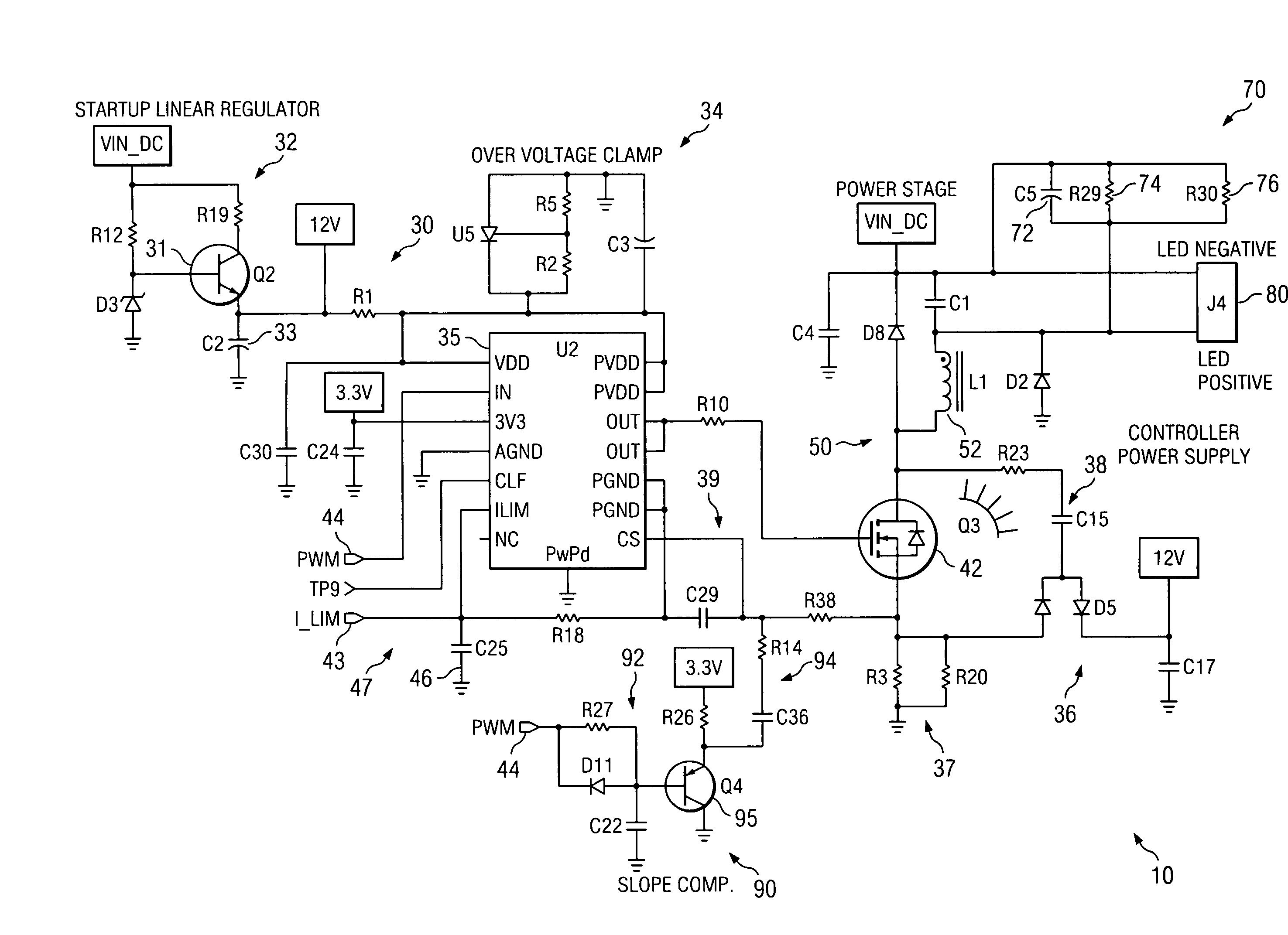
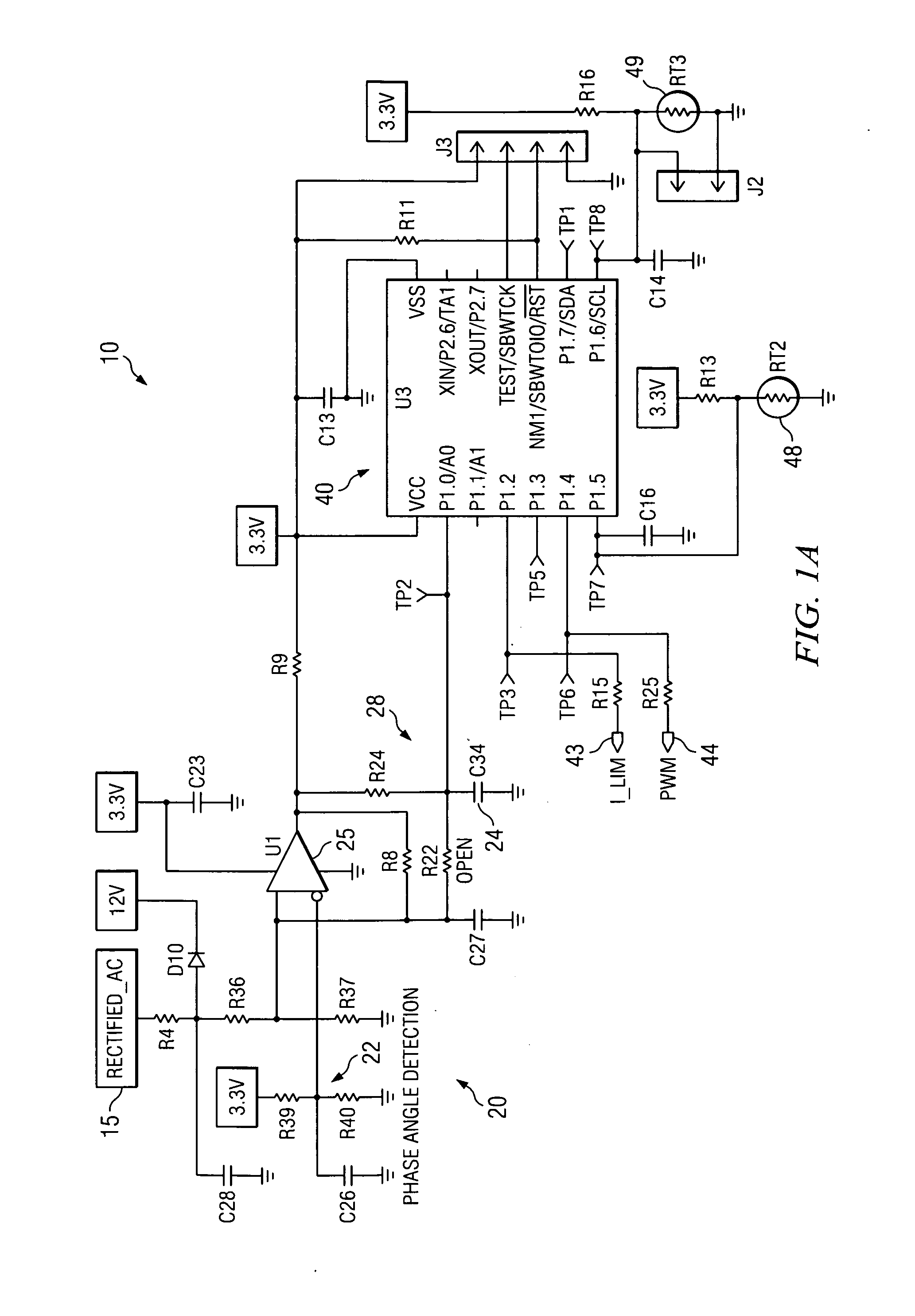
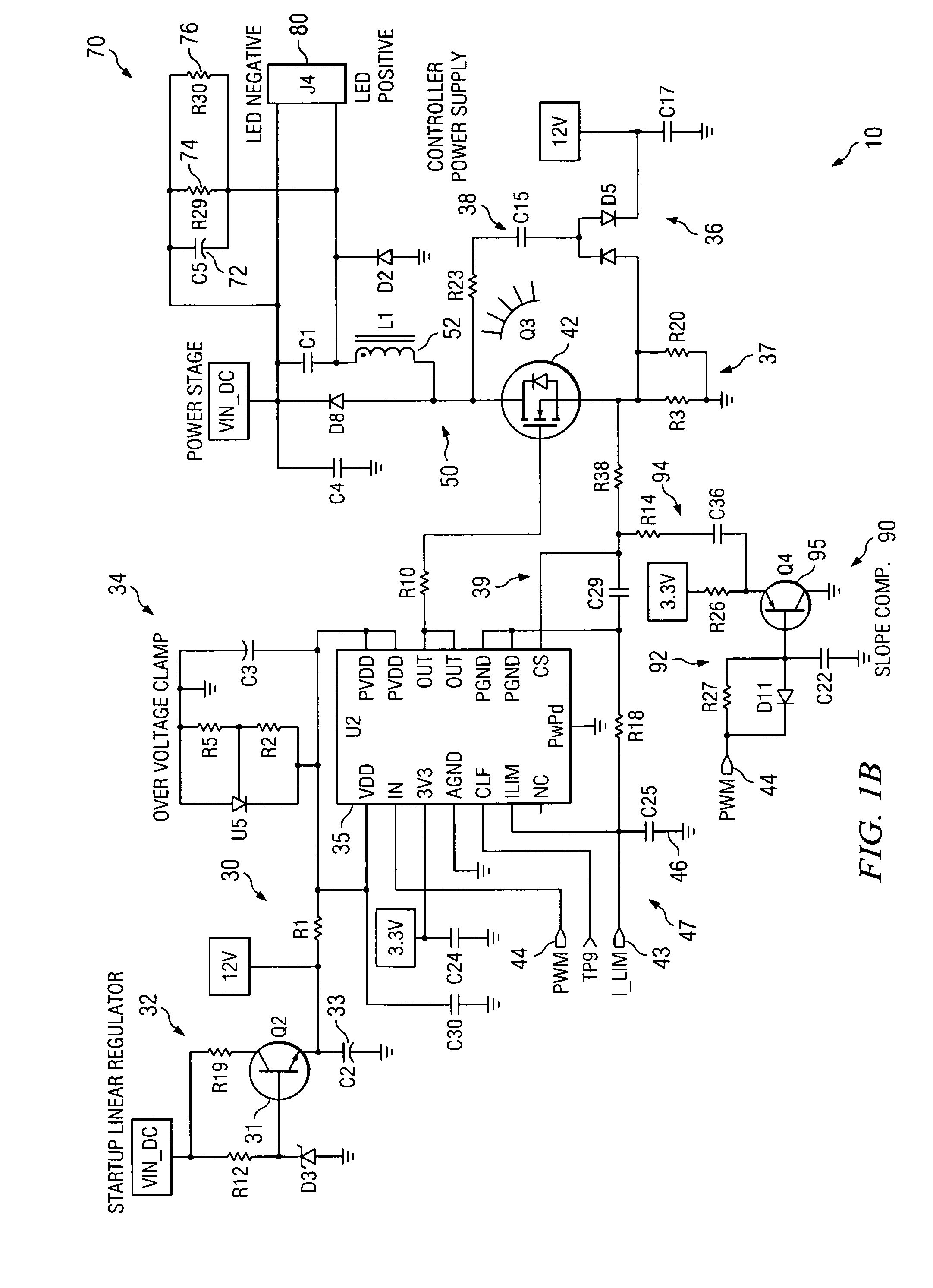
[0019]An illustrative schematic diagram for a phase-control, PWM-based dimming circuit 10 is shown as FIG. 1. The dimming circuit 10 provides power to a light source(s) 80 and includes a phase-angle detection circuit 20, a controller power supply 30, a controller 40, a power stage 50, a dv / dt filter 60, an optional output filter 70, and an optional slope compensation circuit 90.

[0020]Although the invention will be described in connection with a TRIAC, those of ordinary skill in the art can appreciate that proportional-current PMW-dimming control can also be accomplished using an integrated gate bi-polar transistor (IGBT).

Phase-Angle Detection Circuit

[0021]The phase-angle detection circuit 20 is structured and arranged to sense input voltage (VIN) from a conventional, phase-controlled 120 VAC, 60 Hz power source 15, such as a standard AC outlet, and to provide a filtered, DC pulse signal to the controller 40 that is based on the sensed input voltage and pseudo-representative of the i...


PUM


Abstract

A dimmable, light-emitting diode (LED) power supply adapted to provide a direct current (DC), constant current (“constant current source”) from a conventional, phase-controlled 120 VAC, 60 Hz power source is disclosed. The constant current source of the present invention utilizes two processes to control dimming. In a first process, the phase angle of the input voltage is used to control the duty cycle of a line frequency pulse width modulation (PWM). In a second process, a proportional-current limit adjustment is used to control the average current to the LED during the ON time of the line frequency by PWM. As a result, at relatively low phase angles, peak currents can be lowered, reducing flicker and improving the audible noise levels generated by the circuit.

Description

CROSS REFERENCE TO RELATED APPLICATIONS[0001]Not ApplicableSTATEMENT REGARDING FEDERALLY SPONSORED RESEARCH OR DEVELOPMENT[0002]Not ApplicableBACKGROUND OF THE INVENTION[0003]Light-dimming is effected by adjusting the magnitude and / or the time of application of current to a light source(s). For example, control and dimming of a light source(s) using pulse width modulation (PWM) is well-known to those of ordinary skill in the relevant art. PWM-dimming works by varying the amount or length of time a switching device, such as a TRIAC, is in an ON state during a cycle relative to the total cycle time. This is referred to as the “duty cycle”. Typically, PWM-dimming supplies power (current) to the light source when an input voltage is above a threshold voltage (ON), and withholds power when the input voltage is below the threshold voltage (OFF). The longer the duty cycle, the relatively-brighter the light source(s), and the shorter the duty cycle, the relatively dimmer the light source(s)...

Claims


Application Information

Patent Timeline
Patent Type & Authority Applications(United States)
IPC IPC(8): H05B41/36
CPCH05B33/0818Y02B20/347H05B33/0851H05B45/10Y02B20/30H05B45/375H05B45/18
Inventor DAHLMAN, MARK COBBGLENN, JOHN CHARLES
Owner TEXAS INSTR INC
Why Eureka
Try Eureka