Directional linear light source

a linear light source and directional technology, applied in the field of light arts, can solve the problems of phosphor degradation, inconvenient illumination applications, and phosphor degradation, and achieve the effect of enhancing light coupling

Active Publication Date: 2009-07-02
GE LIGHTING SOLUTIONS LLC
View PDF15 Cites 162 Cited by
  • Summary
  • Abstract
  • Description
  • Claims
  • Application Information

AI Technical Summary

Benefits of technology

[0008]In accordance with certain illustrative embodiments shown and described as examples herein, an illumination apparatus is disclosed, comprising: a linear array of light emitting diode (LED) chips disposed on a support; a linear reflector assembly having a light coupling reflector portion and a one-dimensional light collimation or focusing portion, the linear reflector assembly being secured to the support parallel with the linear array of LED chips; an encapsulant disposed in the light coupling reflector portion of the linear reflector assembly and potting the LED chips; and an elongate phosphor element disposed over the encapsulant such that the light coupling reflector portion and the encapsulant enhance light coupling between the LED chips and the elongate phosphor element and the one-dimensional light collimation or focusing portion one-dimensionally collimates or focuses light emitted by the combination of the LED chips and the elongate phosphor element.

Problems solved by technology

LED devices generally emit light over a relatively narrow spectral range, which is not suitable for typical illumination applications.
However, it has also been recognized that a difficulty with this combination is that the phosphor can degrade over time.
Phosphor degradation has been observed in various LED / phosphor combinations, and is particularly problematic in white devices that combine an LED emitting in the blue, violet, or ultraviolet range with a white phosphor composition.
Phosphor degradation typically results from heating.
Existing LED / phosphor combinations are generally not well-suited for such applications.

Method used


Image

  • Directional linear light source
  • Directional linear light source
  • Directional linear light source

Examples


Embodiment Construction

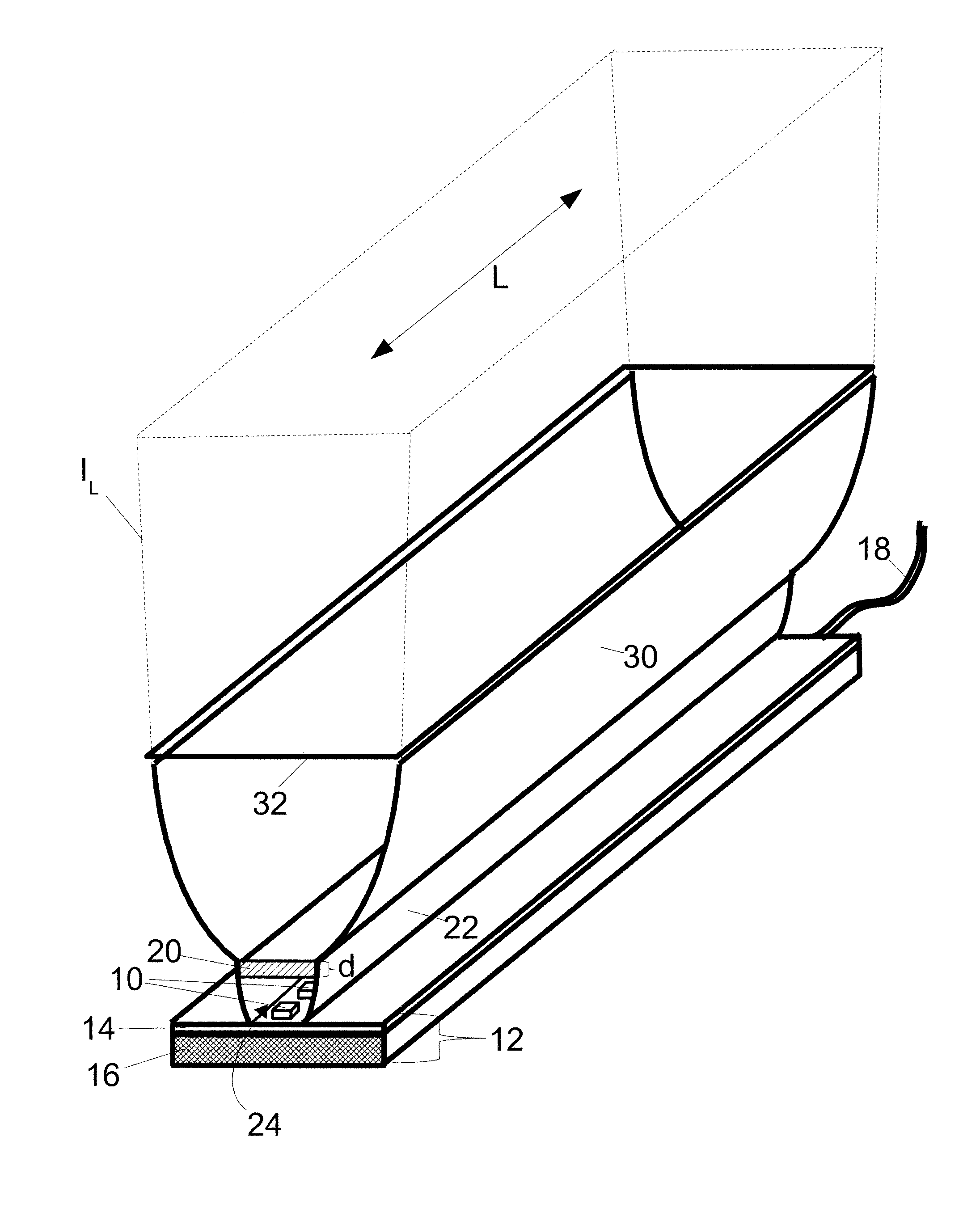
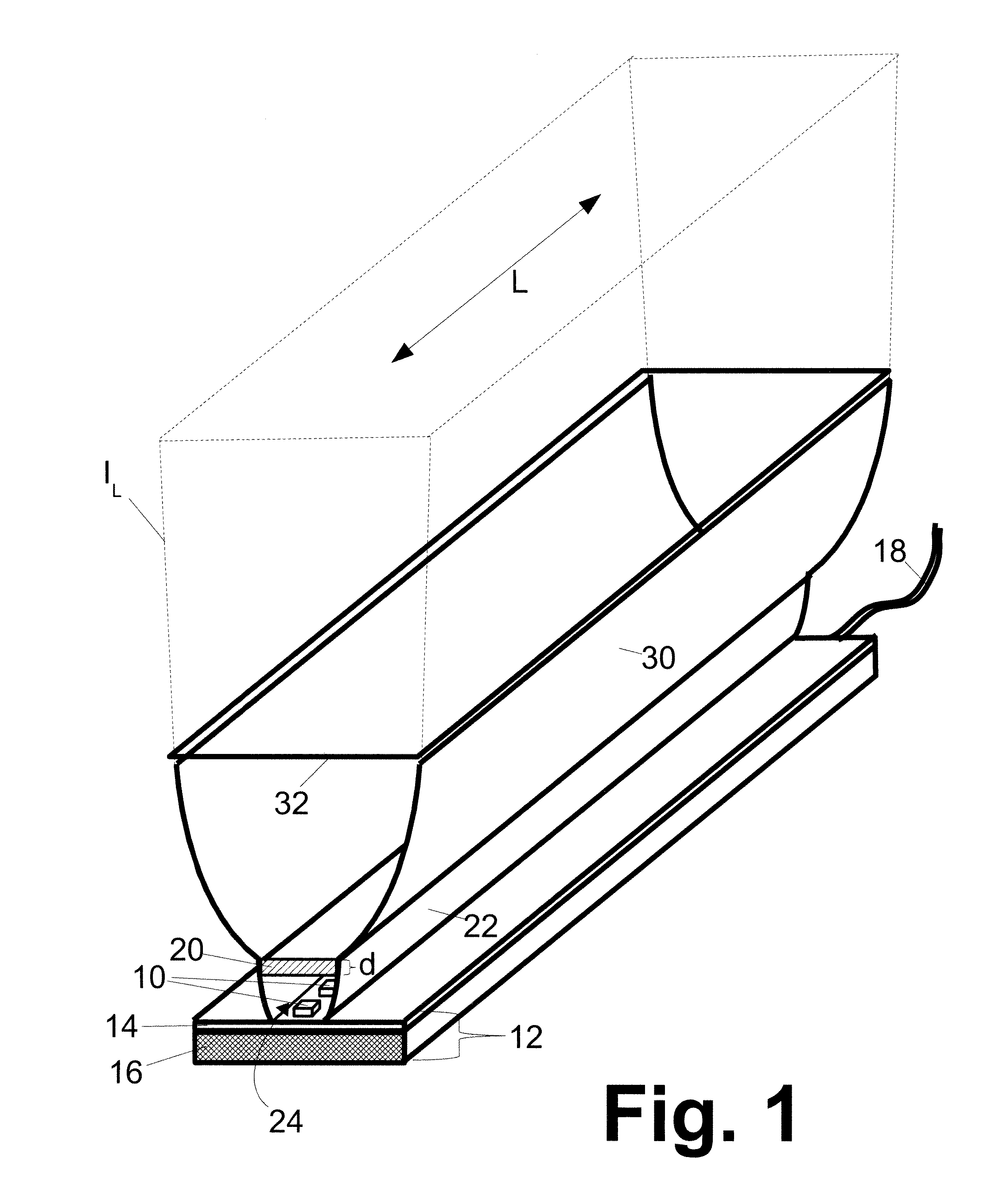
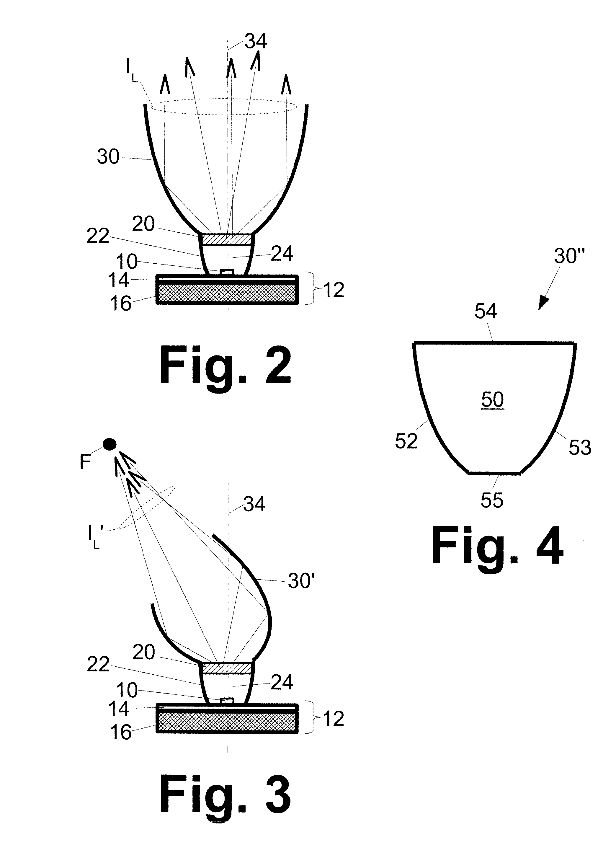
[0016]With reference to FIGS. 1 and 2, a linear light source includes a linear array of light emitting diode (LED) chips 10 disposed on a support 12. The linear array of LED chips 10 is parallel with a linear direction or direction of elongation denoted by the double-headed arrow L in FIG. 1. The LED chips 10 may be group III-nitride LED chips, group III-phosphide LED chips, group III-arsenide LED chips, or so forth, and may be configured as vertical chips, lateral chips, surface mount chips, flip-chip devices, or so forth, and may be either bare chips or packaged chips disposed, for example, in a lead frame or on a submount. In the illustrated embodiment, the support circuit board 14 disposed on a metal plate 16 or other thermally conductive heat sink. The circuit board 14 includes suitable printed circuitry or other electrical pathways (not shown) for interconnecting the LED chips 10 with an electrical power supply (not shown) via a power cord 18 or other power input pathway. Alth...


PUM


Abstract

An illumination apparatus includes a linear array of light emitting diode (LED) chips disposed on a support. A linear reflector assembly has a light coupling reflector portion and a one dimensional light collimation or focusing portion. The linear reflector assembly is secured to the support parallel with the linear array of LED chips. An encapsulant is disposed in the light coupling reflector portion of the linear reflector assembly and pots the LED chips. An elongate phosphor element is disposed over the encapsulant such that the light coupling reflector portion and the encapsulant enhance light coupling between the LED chips and the elongate phosphor element, and the one-dimensional light collimation or focusing portion one-dimensionally collimates or focuses light emitted by the combination of the LED chips and the elongate phosphor element.

Description

BACKGROUND[0001]The following relates to the lighting arts. It finds application for example in general illumination, accent lighting, architectural lighting, and so forth.[0002]The combination of light emitting diode (LED) devices with wavelength-converting phosphor has well understood advantages. LED devices generally emit light over a relatively narrow spectral range, which is not suitable for typical illumination applications. By coupling LED devices with wavelength converting phosphor, light of broader spectrum can be generated, including various spectrums corresponding to white light.[0003]However, it has also been recognized that a difficulty with this combination is that the phosphor can degrade over time. Phosphor degradation has been observed in various LED / phosphor combinations, and is particularly problematic in white devices that combine an LED emitting in the blue, violet, or ultraviolet range with a white phosphor composition. Phosphor degradation typically results fr...

Claims


Application Information

Patent Timeline
Patent Type & Authority Applications(United States)
IPC IPC(8): F21V9/16F21S4/00
CPCF21S4/008F21S8/032F21V7/005F21V9/10F21Y2103/003F21V31/04F21Y2101/02F21S4/28F21Y2103/10F21Y2115/10F21V13/08F21V9/32
Inventor MRAKOVICH, MATTHEW S.MAYER, MARK J.
Owner GE LIGHTING SOLUTIONS LLC
Why Eureka
Try Eureka