
Method of manufacturing composite material

Inactive Publication Date: 2009-07-02
AIRBUS OPERATIONS LTD
View PDF25 Cites 35 Cited by
  • Summary
  • Abstract
  • Description
  • Claims
  • Application Information

AI Technical Summary

Benefits of technology

[0012]Growth of the reinforcement layers may be enhanced by forming a plasma during growth of the or each layer. This enables growth to be carried out at lower temperatures, typically in the range of 25-500° C.
[0013]The layers of reinforcement may be grown in-situ by an arc discharge process, in which stock material contained in a negative electrode sublimates because of the high temperatures caused by the discharge. Alternatively the layers of reinforcement may be grown in-situ by a laser ablation process, in which a pulsed laser vaporizes a target in a high temperature reactor while an inert gas is bled into a process chamber. The reinforcement layers develop on the cooler surfaces of the reactor, as the vaporized material condenses. In the case of arc discharge or laser ablation, the elements (such as carbon nanotubes) making up the reinforcement layers are formed in a gaseous state, and in-situ growth of the layers occurs by condensation of the elements on a substrate. However a problem with such arc discharge and laser ablation processes is that they are not suited to high volume production, and tend to require high temperatures. Therefore preferably the method further comprises forming one or more layers of catalyst particles to catalyse the growth of the reinforcement, for instance as part of a chemical vapour deposition process. This enables growth to be carried out at lower temperatures, typically in the range of 25-500° C. In this case the layers grow by in-situ growth of the elements making up the reinforcement layers, instead of growing by accumulation of preformed elements.
[0017]In the embodiment described below, 100% of the matrix material consists of such a catalytic matrix material. However it will be understood that the matrix material may have more than one phase, in which case over 50% by weight of the matrix comprises catalytic material. The advantage of using a catalytic matrix material is that there is no need to perform the separate step of depositing a distinct layer of catalyst particles on top of a previously deposited layer of matrix.
[0025]At least two of the layers of reinforcement may be impregnated and / or grown with different shapes. This enables the composite material to form any desired shape, in the manner of a so-called “additive layer manufacturing” or “rapid manufacturing” process.
[0026]At least two of the layers of reinforcement may also be grown with different packing densities. Furthermore, at least one of the layers of reinforcement may be grown with a packing density which varies across the layer. This enables the material to be selectively reinforced.

Problems solved by technology

According to this paper, one of the most significant challenges towards improving the properties of the nanocomposite is to obtain a uniform dispersion of nanotubes within the polymer matrix.

Method used


Image

  • Method of manufacturing composite material
  • Method of manufacturing composite material
  • Method of manufacturing composite material

Examples


Embodiment Construction

)

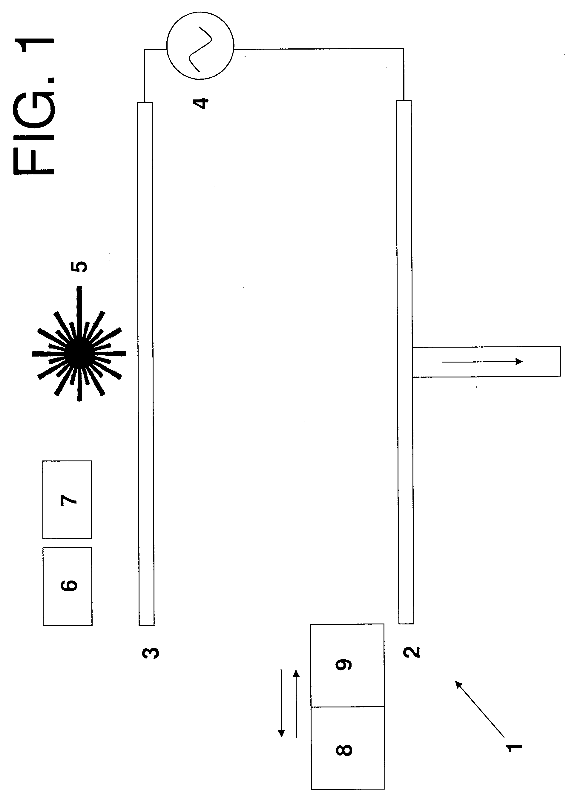
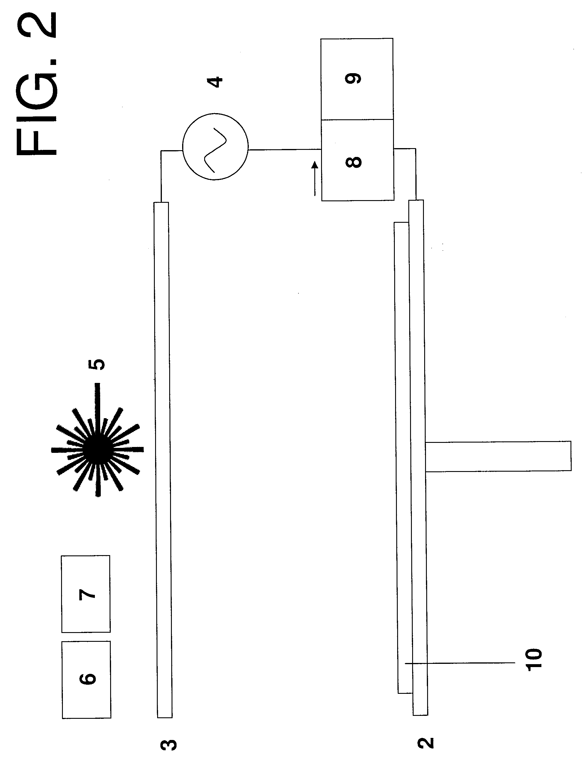
[0037]The apparatus 1 shown in FIG. 1 is housed within a process chamber (not shown). A negative plasma source electrode 2 and a positive plasma source electrode 3 are connected by a power source 4. A laser 5 is positioned above the positive plasma source 3, and is associated with a raster scanning mechanism (not shown). A gas supply 6 can be turned on and off to supply a pre-heated process gas to the chamber, such as CH4 / H2. A second gas supply 7 can be turned on and off to supply an inert gas such as N2 to the process chamber. The inert gas is preheated to a temperature at or just below the melting point of the matrix material. The electrode 2 is also heated by a heating element (not shown) to a similar temperature.

[0038]A heated hopper 8 and a cooled ink-jet printing head 9 are mounted on a transport mechanism (not shown) which can move the hopper 8 and printing head 9 from left to right in FIG. 1 (that is, from one end of the negative plasma source 2 to the other). A transport ...


PUM

PropertyMeasurementUnit
Percent by massaaaaaaaaaa
Weightaaaaaaaaaa
Thicknessaaaaaaaaaa

Abstract

A method of manufacturing a composite material, the method comprising: growing two or more layers of reinforcement in-situ; and impregnating each layer with a matrix before growing the next layer. The reinforcement layers may be formed by a chemical vapour deposition process. The method can be used as an additive layer manufacturing technique to form a component with a desired shape and physical characteristics.

Description

FIELD OF THE INVENTION[0001]The present invention relates to a method of manufacturing a composite material.BACKGROUND OF THE INVENTION[0002]Nanocomposites based on carbon nanotubes are described in E. T. Thostenson and T-W. Chou, “Aligned Multi-Walled Carbon Nanotube-Reinforced Composites: Processing and Mechanical Characterization,”Journal of Physics D: Applied Physics, 35(16) L77-L80 (2002). According to this paper, one of the most significant challenges towards improving the properties of the nanocomposite is to obtain a uniform dispersion of nanotubes within the polymer matrix. The solution presented in this paper is a micro-scale twin-screw extruder.SUMMARY OF THE INVENTION[0003]A first aspect of the invention provides a method of manufacturing a composite material, the method comprising:[0004]growing two or more layers of reinforcement in-situ; and[0005]impregnating each layer with a matrix before growing the next layer.[0006]A further aspect of the invention provides a compo...

Claims


Application Information

Patent Timeline
IPC IPC(8): B32B3/30C23C14/00C23C4/00C23C8/00B05C11/00
CPCB29C70/14B29C70/30Y10T428/2457B82Y30/00B29C70/62B33Y70/00
Inventor FARMER, BENJAMIN LIONELJOHNS, DANIEL MARKPRICE, JOHN MAURICE
Owner AIRBUS OPERATIONS LTD
Learn More