
Cmp system and method using individually controlled temperature zones

Active Publication Date: 2009-07-02
ADVANCED MICRO DEVICES INC
View PDF4 Cites 19 Cited by
  • Summary
  • Abstract
  • Description
  • Claims
  • Application Information

AI Technical Summary

Benefits of technology

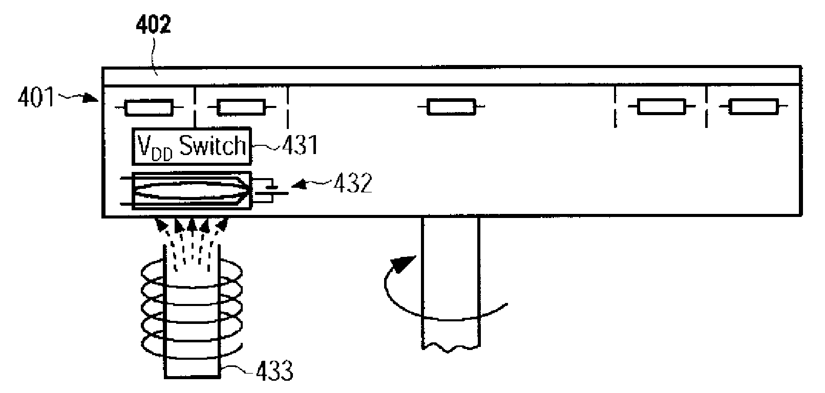
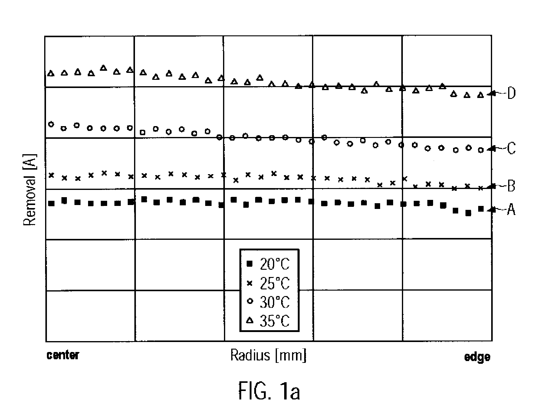
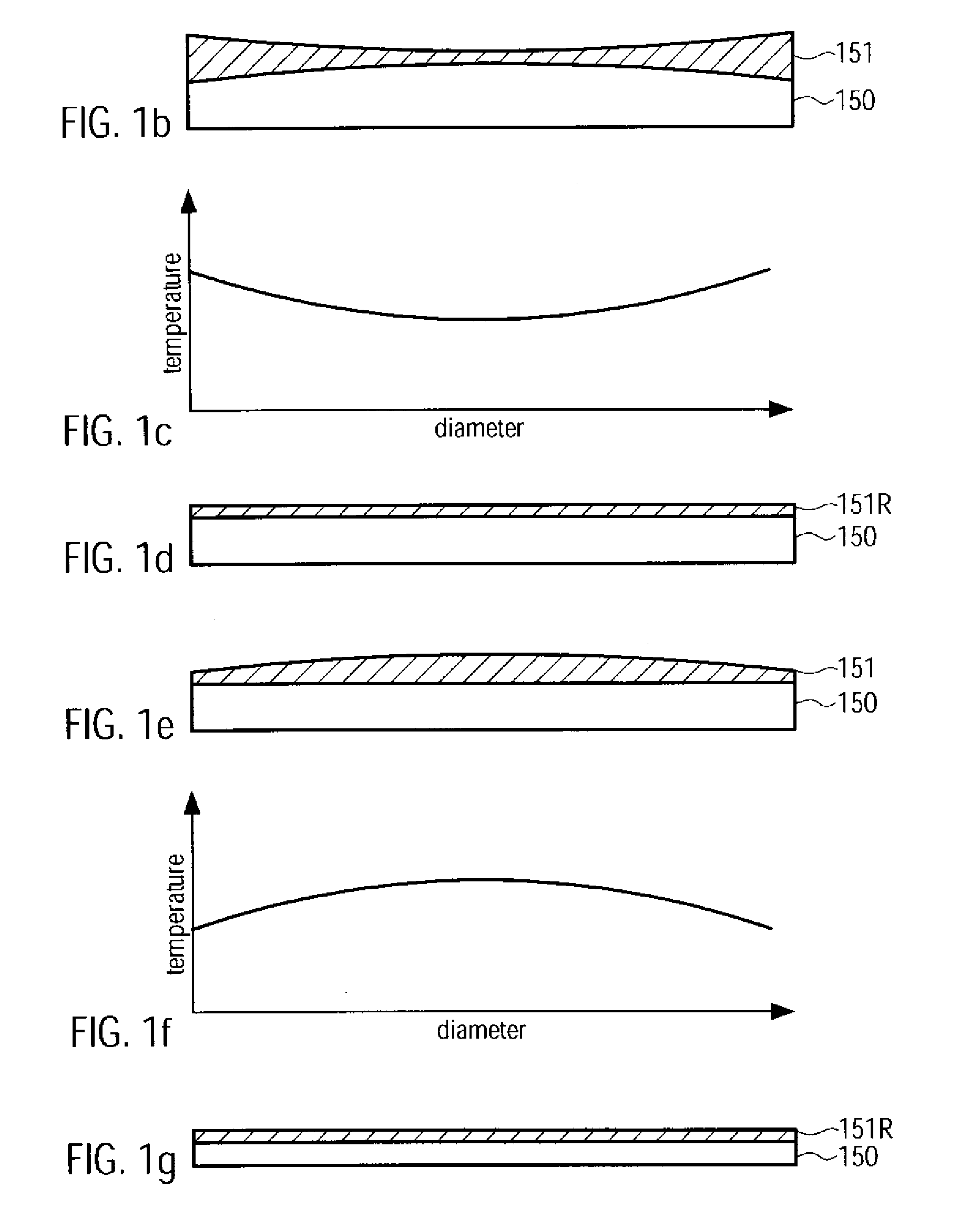
[0012]Generally, the present disclosure relates to methods and a system for removing material from microstructure substrates, such as semiconductor devices, on the basis of a polishing process, in which a removal rate profile across the substrate may be adjusted on the basis of an appropriate temperature control, which may be highly efficient in combination with a chemically activated removal mechanism, as may be provided by a chemically highly reactive slurry material that typically exhibits a significant temperature dependency. In other cases, in electrochemical polishing processes, the redox potential may also exhibit a significant temperature dependency, thereby enabling a respective profiling of the removal rate across individual substrates. Consequently, efficient control strategies may be established on the basis of the temperature dependent removal mechanism, thereby improving controllability and enabling feedback and / or feed forward strategies, which may otherwise be difficult to achieve according to conventional control regimes.

Problems solved by technology

In other cases, any unwanted material may have to be removed, wherein typically used etch techniques may be less appropriate.
The polishing process itself causes mechanical damage to the polished surface, however, in an extremely low range, i.e., at an atomic level, depending on the process conditions.
However, the reduced relative permittivity is typically associated with a reduced mechanical stability of the corresponding materials, thereby resulting in highly fragile dielectric layer stacks, from which excess material, such as copper, has to be removed, for instance, by CMP or electrochemical CMP.
Due to the reduced mechanical stability of sophisticated dielectric materials, however, the down force during the polishing process may have to be increasingly reduced to an amount that is compatible with mechanical characteristics of the low-k dielectrics.
However, a respective increase of the relative motion may not necessarily translate into a higher removal rate in this polishing regime using extremely low down forces and, hence, in addition to a loss of process controllability, process efficiency may be reduced.
Furthermore, other parameters such as the slurry flow and the like may be controlled in addition to the platen speed or the head speed, wherein, however, a highly complex mutual interaction of these parameters may require the development of highly complex process recipes, which may be difficult to be controlled in a feed forward or feedback regime, thereby contributing to reduced overall controllability and also to an increased probability of creating additional yield loss.
However, the process control may still be very complex and less efficient, since an enhanced chemical contribution to the overall removal rate may not efficiently “respond” to a variation of process conditions when controlling the complex substantially “mechanical contributions” represented by slurry supply and relative speeds of the platen and the substrate, in combination with a significantly reduced downward pressure.

Method used


Image

  • Cmp system and method using individually controlled temperature zones
  • Cmp system and method using individually controlled temperature zones
  • Cmp system and method using individually controlled temperature zones

Examples


Embodiment Construction

[0029]Various illustrative embodiments of the invention are described below. In the interest of clarity, not all features of an actual implementation are described in this specification. It will of course be appreciated that in the development of any such actual embodiment, numerous implementation-specific decisions must be made to achieve the developers' specific goals, such as compliance with system-related and business-related constraints, which will vary from one implementation to another. Moreover, it will be appreciated that such a development effort might be complex and time-consuming, but would nevertheless be a routine undertaking for those of ordinary skill in the art having the benefit of this disclosure.

[0030]The present subject matter will now be described with reference to the attached figures. Various structures, systems and devices are schematically depicted in the drawings for purposes of explanation only and so as to not obscure the present disclosure with details ...


PUM

PropertyMeasurementUnit
Temperatureaaaaaaaaaa
Dielectric polarization enthalpyaaaaaaaaaa
Sizeaaaaaaaaaa

Abstract

By creating a temperature profile across a polishing pad, a respective temperature profile may be obtained in a substrate to be polished, which may result in a respective varying removal rate across the substrate for a chemically reactive slurry material or for an electro-chemically activated polishing process. Hence, highly sensitive materials, such as material comprising low-k dielectrics, may be efficiently polished with a high degree of controllability.

Description

BACKGROUND OF THE INVENTION[0001]1. Field of the Invention[0002]Generally, the subject matter disclosed herein relates to the field of manufacturing integrated circuits, and, more particularly, to a chemical mechanical polishing (CMP) process used for the formation of advanced microstructure devices, such as the metallization structures, including fragile dielectric materials.[0003]2. Description of the Related Art[0004]Typically, the fabrication of modern integrated circuits requires a large number of individual process steps, wherein a typical process sequence involves the deposition of conductive, semiconductive or insulating layers on an appropriate substrate. After deposition of the corresponding layer, device features are produced by patterning the corresponding layer with well-known means, such as photolithography and etching. As a consequence, by patterning a deposited layer, a certain topography will be created that also affects deposition and patterning of subsequent layer...

Claims


Application Information

Patent Timeline
IPC IPC(8): H01L21/306B24B49/14B24B37/015
CPCB24B37/015H01L21/32125H01L21/3212
Inventor HEINRICH, JENSMARXSEN, GERD
Owner ADVANCED MICRO DEVICES INC
Features
  • Generate Ideas
  • Intellectual Property
  • Life Sciences
  • Materials
  • Tech Scout
  • Unparalleled Data Quality
  • Higher Quality Content
  • 60% Fewer Hallucinations
Learn More