

Crystallographically-oriented ceramic
a crystallographic and oriented technology, applied in the field of crystallographic oriented ceramics, can solve the problems of insufficient piezoelectric/electrostrictive properties, insufficient improvement of piezoelectric/electrostrictive properties, and insufficient durability, so as to achieve the effect of reducing durability, enhancing piezoelectric/electrostrictive properties, and low efficiency
- Summary
- Abstract
- Description
- Claims
- Application Information
AI Technical Summary
Benefits of technology
Problems solved by technology
Method used
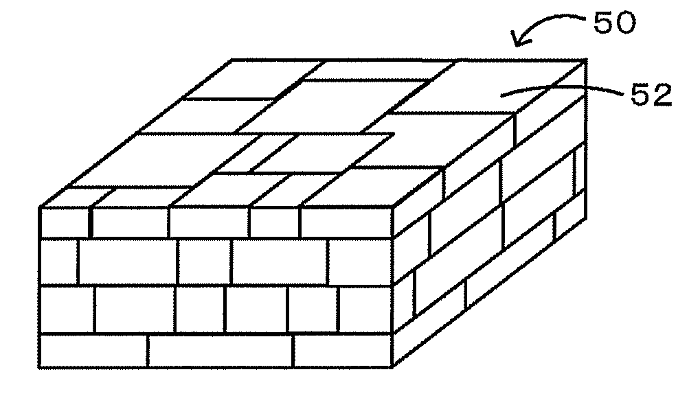
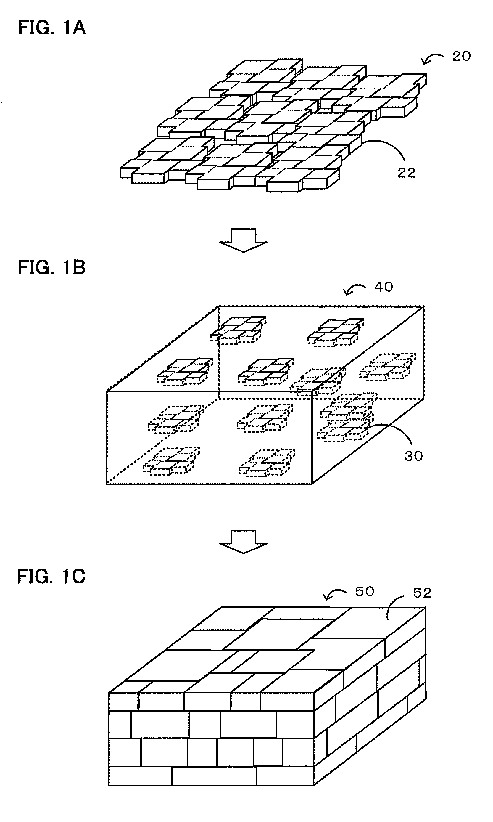
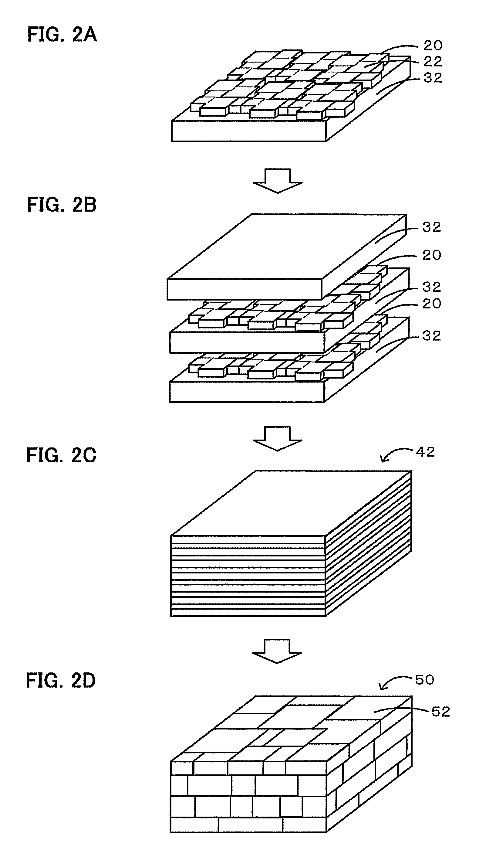
Image

Examples
example 1
[0033]Formation Step of Forming Ceramic Sheet
[0034]ZnO—B2O3—SiO2 glass powder (ASF1891 manufactured by Asahi Glass (AGG)) (0.5% by weight) was mixed with a synthesized powder having the composition, after grain growth, 0.2Pb(Mg0.33Nb0.67)O3-0.35PbTiO3-0.45PbZrO3 to which 1% by weight of NiO was added. The weighed mixture, zirconia balls, and ion-exchanged water as a dispersion medium were placed in a plastic pot, and wet mixing was performed using a ball mill for 16 hours. The resulting slurry was dried using a dryer, and then calcination was performed at 800° C. for 2 hours. The calcined powder, zirconia balls, and ion-exchanged water as a dispersion medium were subjected to wet pulverization using a ball mill for 5 hours, followed by drying using a dryer. Thereby, powder of first inorganic particles was obtained. The resulting first inorganic particles, polyvinyl butyral (BM-2, manufactured by Sekisui Chemical Co., Ltd.) as a binder, a plasticizer (DOP, manufactured by Kurogane Ka...
example 2
[0038]In the formation step of forming a ceramic sheet, 0.5% by weight of MgO was added to a synthesized powder having the composition, after grain growth, 0.2Pb(Mg0.33Nb0.67)O3-0.35PbTiO3-0.45PbZrO3 to which 0.5% by weight of NiO was added. Then, as in Example 1, the slurry was formed into a sheet on a PET film such that the thickness after drying was 1 μm. The shaped body peeled off from the PET film was cut into a 50-mm square with a cutter and placed in the center of a setter made of zirconia (size 60 mm square, height 5 mm). The shaped body was placed in a sheath made of magnesia (size 90 mm square, height 50 mm), with 5 g of powder having the composition of 0.2Pb(Mg0.33Nb0.67)O3-0.35PbTiO3-0.45PbZrO3 being allowed to coexist, and subjected to degreasing at 600° C. for 2 hours, and then firing was performed at 1,280° C. for 2 hours. Then, as in Example 1, a ceramic sheet used for a crystallographically-oriented ceramic was obtained. Furthermore, second inorganic particles were ...
example 3
[0039]In the formation step of forming a ceramic sheet, a ceramic sheet used for a crystallographically-oriented ceramic was obtained as in Example 2 except that the composition, after grain growth, was set to be 0.2Pb(Mg0.33Nb0.67)O3-0.35PbTiO3-0.45PbZrO3 to which 0.5% by weight of NiO and 1.0% by weight of MgO were added. Furthermore, second inorganic particles were obtained as in Example 1 except that 0.5% by weight of NiO was added to the synthesized powder. Subsequently, in the shaping step / firing step of a crystallographically-oriented ceramic, the resulting ceramic sheet was crushed such that the aspect ratio was not less than or equal to 3. The first inorganic particles and the second inorganic particles were mixed so as to have the composition of 0.2Pb(Mg0.33Nb0.67)O3-0.35PbTiO3-0.45PbZrO3 to which 0.5% by weight of NiO and 0.1% by weight of MgO were added. Then, as in Example 2, a crystallographically-oriented ceramic of Example 3 was obtained.
PUM
| Property | Measurement | Unit |
|---|---|---|
| Percent by mass | aaaaa | aaaaa |
| Fraction | aaaaa | aaaaa |
| Percent by volume | aaaaa | aaaaa |
Abstract
Description
Claims
Application Information