Internal Combustion Engine Stop Controller and Stop Control Method

a technology of internal combustion engine and control method, which is applied in the direction of engines, propulsion parts, machines/engines, etc., can solve the problems of increasing power consumption of power exchange circuits, and achieve the effect of preventing excessive power input to power storage devices and excessive charging

Inactive Publication Date: 2009-07-02
TOYOTA JIDOSHA KK
View PDF10 Cites 30 Cited by
  • Summary
  • Abstract
  • Description
  • Claims
  • Application Information

AI Technical Summary

Benefits of technology

[0027]Therefore, the main advantage of the present invention is that, at the time of stop control of an internal combustion engine in which the internal combustion engine stopping f

Problems solved by technology

Specifically, based on the estimation of power generated by the stop control of internal combustion engine and power consumption by the power exchange circuit,

Method used


Image

  • Internal Combustion Engine Stop Controller and Stop Control Method
  • Internal Combustion Engine Stop Controller and Stop Control Method
  • Internal Combustion Engine Stop Controller and Stop Control Method

Examples


modification 1

[0116](Modification 1)

[0117]There is an upper limit in increase of power consumption realized by changing the state of operation of step-up / down converter 15 and inverters 20 and 30 in accordance with the embodiment of the present invention. Therefore, even when the total power consumption is increased to the upper limit, it is still possible that the power input to the power storage device (battery B for running) exceeds the tolerable range, as shown in FIG. 7. In such a case, it becomes necessary to reduce the amount of power generation or to stop power generation by motor generator MG1, in order to avoid excessive charging of the power storage device.

[0118]FIG. 8 is a flowchart representing a series of control processes in the engine stop control in Modification 1 of the embodiment of the present invention, to deal with this situation.

[0119]Referring to FIG. 8, in engine stop control in accordance with Modification 1 of the embodiment, steps S200 to S220 are executed in addition ...

modification 2

[0124](Modification 2)

[0125]FIG. 9 is a flowchart representing a series of control processes in the engine stop control in Modification 2 of the embodiment of the present invention.

[0126]Referring to FIG. 9, in the engine stop control in accordance with Modification 2 of the embodiment shown in FIG. 7, steps S250 to S270 are executed in addition to the process of the flowchart shown in FIG. 7.

[0127]If the determination at step S140 is YES, that is, if the estimated input power Pb reflecting the total power consumption Ptt1 at the current state of operation exceeds the tolerable range, controller 50 estimates an upper limit of total power consumption Ptt1max that can be attained by changing the state of operation at step S250 and, calculates the estimated input power Pb# to the power storage device (battery B for running) at this time.

[0128]Further, at step S260, controller 50 determines whether or not the estimated input power Pb# of step S250 exceeds the tolerable range. Specifical...


PUM


Abstract

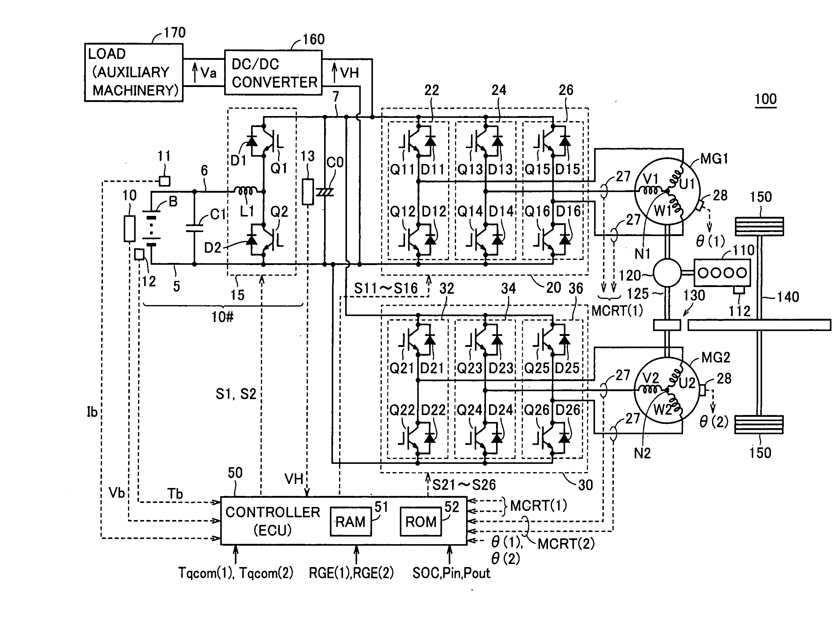
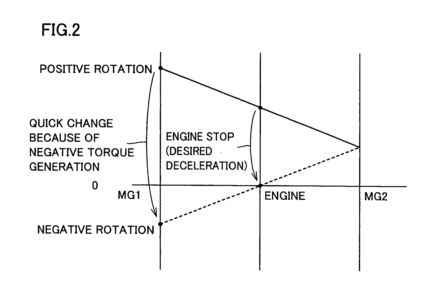
When engine stop control is executed, an ECU estimates input power to a power storage device in accordance with an estimation of power generated by a generator and estimation of total power consumption of circuitry from the generator to the power storage device in the current state of operation. Further, the ECU compares the estimated input power with a tolerable input power to the storage device. When the generated power is excessive, the state of operation of the circuitry is changed such that the total power consumption by the circuitry increases, and then, torque output of the generator is permitted, to attain desired deceleration at the engine stop. Accordingly, in the engine stop control in which stopping force is generated by the power generating operation by the rotating electric machine, excessive charging caused by excessive power input to the power storage device can be prevented.

Description

TECHNICAL FIELD[0001]The present invention relates to a stop controller and a stop control method for an internal combustion engine and, more specifically, to stop control of an internal combustion engine in a vehicle in which stopping force for the internal combustion engine can be generated by a power generating operation of a rotating electric machine.BACKGROUND ART[0002]A vehicle mounting a power train combining an internal combustion engine (by way of example, use of a known engine such as a gasoline engine or a diesel engine may be possible) and a rotating electric machine (motor generator or the like), referred to as a hybrid system, has been developed and put to practical use. In such a vehicle, output share of an operation by the internal combustion engine (hereinafter also referred to as an engine) and an operation by the rotating electric machine is automatically switched independent from an amount of accelerator operation by the driver, to be regulated to attain the high...

Claims


Application Information

Patent Timeline
IPC IPC(8): G06F19/00B60K6/445B60L50/16B60W10/06B60W10/08B60W10/26B60W20/00F02D29/02F02D29/06H02P27/06
CPCB60K6/445B60W20/40B60L11/1872B60L15/2045B60L2260/54B60W10/06B60W10/08B60W10/26B60W20/00F02D29/06Y02T10/6286Y02T10/7005Y02T10/7044Y02T10/705Y02T10/7283B60L11/123B60L11/14B60L2210/40Y02T10/6239Y02T10/7077Y02T10/7241Y02T10/6217B60W2710/244B60W2710/248B60L11/1862B60L50/61B60L50/16B60L58/25B60L58/15Y02T10/62Y02T10/70Y02T10/64Y02T10/72Y02T10/7072B60W20/13
Inventor YAGUCHI, HIDEAKI
Owner TOYOTA JIDOSHA KK
Why Eureka
Try Eureka