Inline processing and irradiation system

a technology of irradiation system and conveyor system, which is applied in the direction of transportation and packaging, instruments, and packaged goods types, can solve the problems of not being able to be placed into an inline manufacturing layout, the full system including the accelerator, radiation shielding and material handling conveyor system can be rather large, and the heating of packaged goods, etc., to achieve the effect of preserving the mechanical integrity of the device, reducing the power requirements of the process, and saving energy

Inactive Publication Date: 2009-07-09
RDI IBA TECH GROUP +1
View PDF14 Cites 19 Cited by
  • Summary
  • Abstract
  • Description
  • Claims
  • Application Information

AI Technical Summary

Benefits of technology

[0016]In the case of sterilization of a medical disposable product such as a syringe, it is important to deliver a sufficient radiation dose to kill the contaminating bacteria while the dose absorbed in the body of the syringe is minimized. This is important because the sterilizing energy may also degrade the mechanical properties of the plastics used in the body of the syringe, thus providing a minimum dose to these materials preserves the mechanical integrity of the device. Additionally, by minimizing the delivered dose we conserve energy and the power requirements for the process are reduced.

Problems solved by technology

The full system including the accelerator, radiation shielding and material handling conveyor system can be rather large, occupying typically thousands of square feet of floor space, and is not conducive to being placed into an inline manufacturing layout.
The drawback of this method of treatment is the packaged goods are heated by the RF and subsequently partially “cooked” in this process.
Also, these prior art systems do not fully combine the efficiencies of in-line form-fill-seal packaging with the benefits of in-line sterilization of the product within the packaging before leaving the form-fill-seal packaging system.
However, these systems do not perform any treatment process using a continuous feed.

Method used


Image

  • Inline processing and irradiation system
  • Inline processing and irradiation system
  • Inline processing and irradiation system

Examples


Embodiment Construction

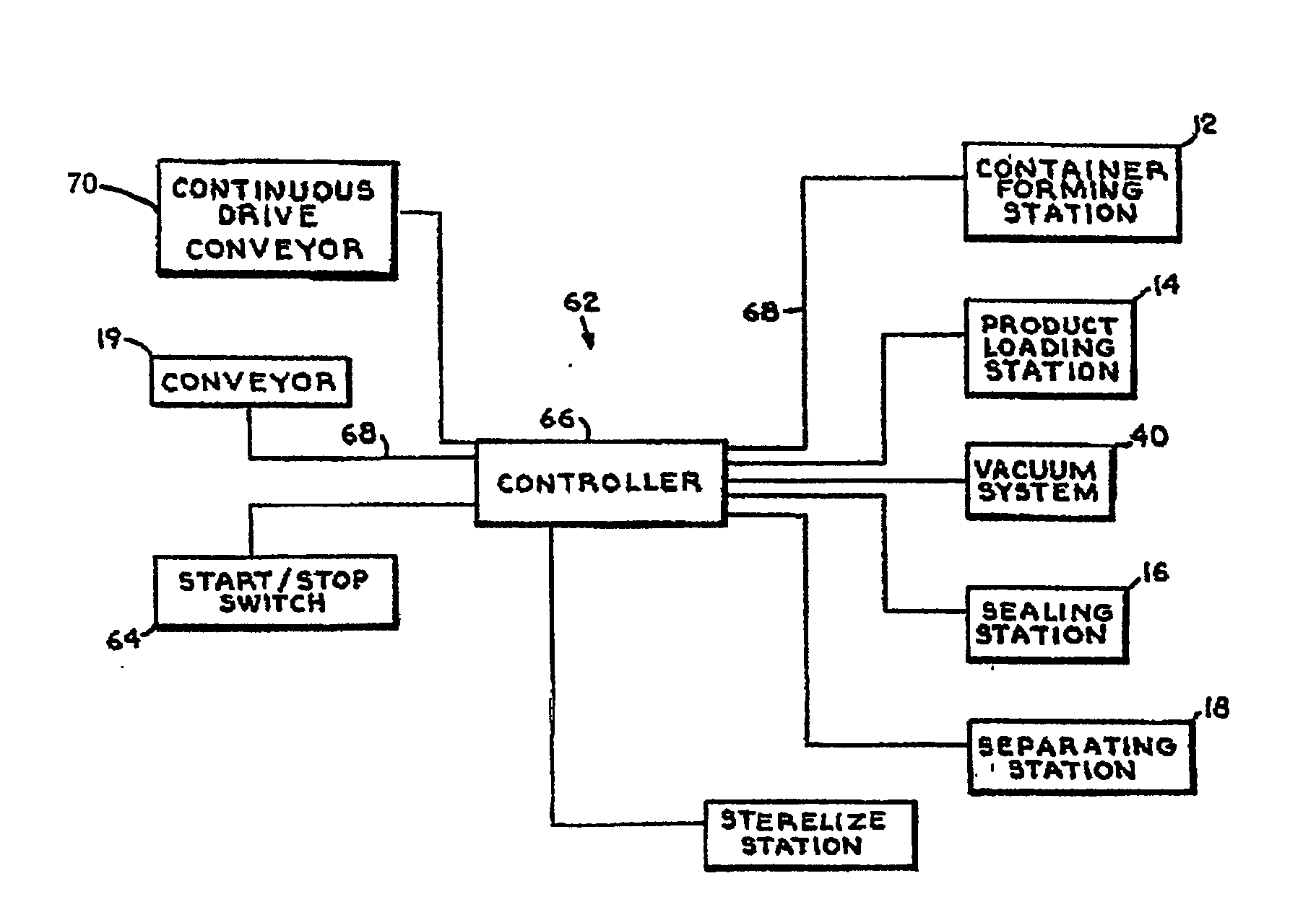
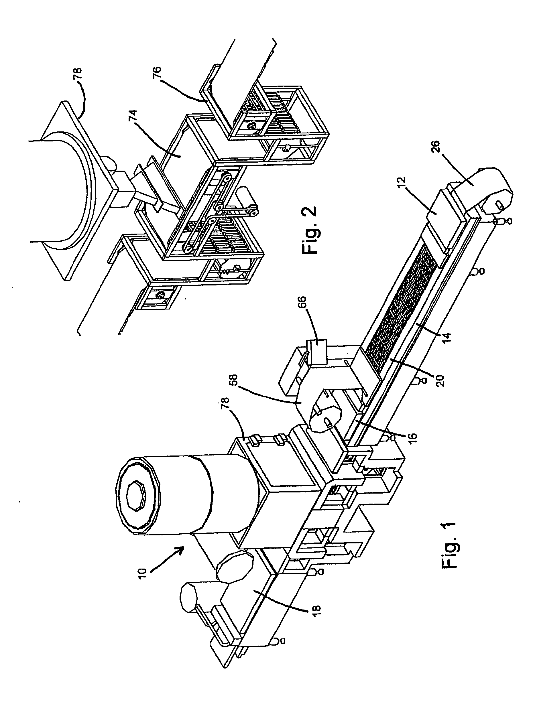
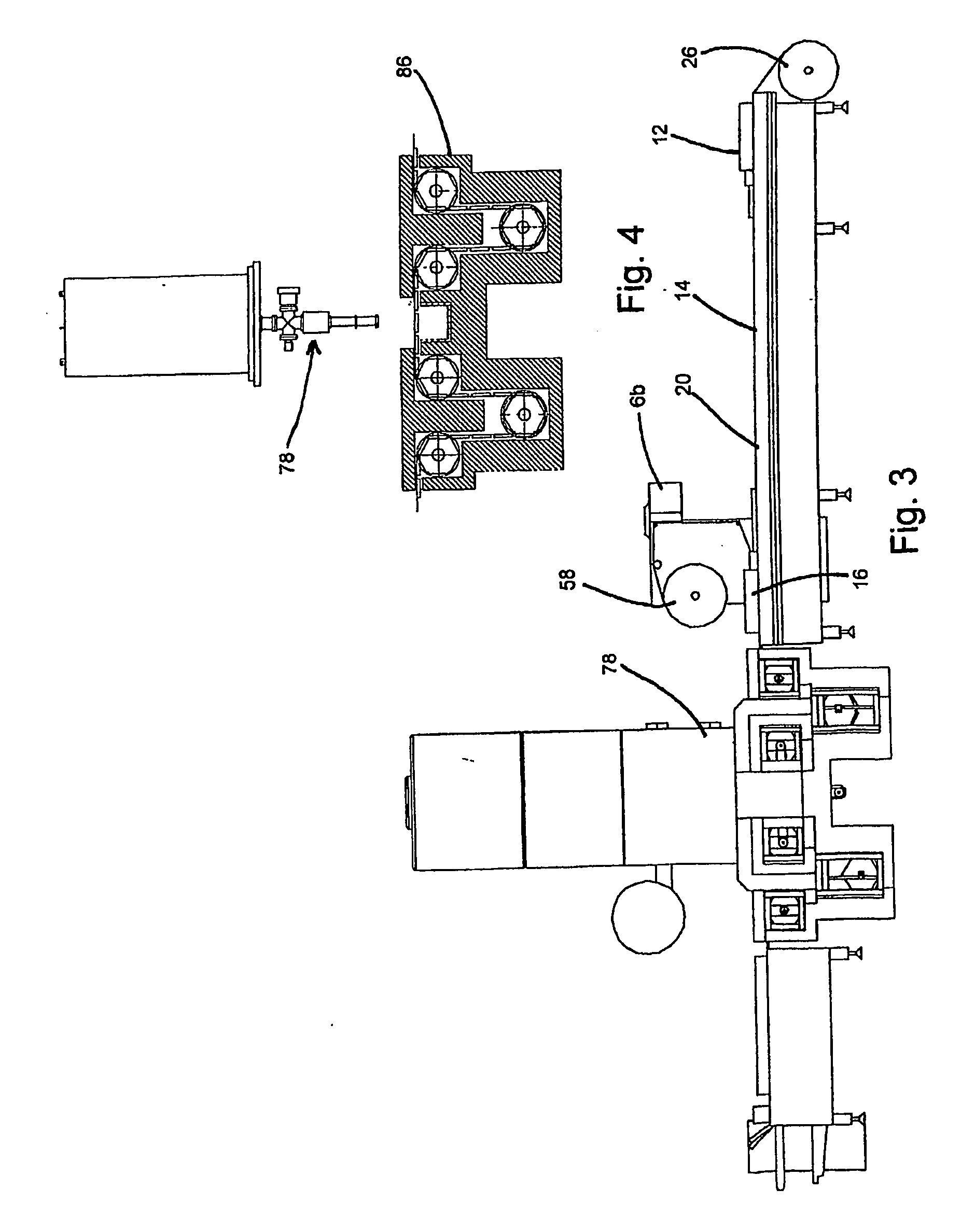
[0031]Referring to the accompanying drawings in which like reference numbers indicate like elements, FIGS. 1-4 illustrate the packaging machine 10 of the present invention according to a first embodiment. Machine 10 comprises a container forming station 12, a product loading station 14, a sealing station 16, a separating station 18 and a conveyor 20. It should be appreciated that while the present invention is described with reference to a packaging machine that can draw a vacuum, it is not necessarily limited to only those in-line form-fill-seal packaging machines with this vacuum capability. The present invention can be used with any type of in-line form-fill-seal packaging machine, including those which use a magazine to load packages onto a conveyor. Additionally, the packaging may be evacuated or be partially filled with an inert gas, air or some other medium or material, possibly even a liquid.

[0032]Conveyor 20 moves incrementally at spaced intervals 96 along the length of the...


PUM

PropertyMeasurementUnit
speedaaaaaaaaaa
beam currentaaaaaaaaaa
diameteraaaaaaaaaa

Abstract

A stream of products is packaged and biologically treated by the system. The system has an index conveyor with a filling station and a packaging station. Discrete packages are filled with the stream of products, sealed and moved on an index conveyor. The system moves the discrete packages an irradiation chamber at a steady rate on a continuous speed conveyor. A controller matches the cyclical rate of the index conveyor with the steady rate of the continuous speed conveyor and uses a buffer to transition from the cyclical rate to the steady rate.

Description

CROSS-REFERENCE TO RELATED APPLICATIONS[0001]This application claims priority to International Patent Application No. PCT / US2004 / 027186, filed on Aug. 20, 2004, which is published as WO 2005 / 019033 and claims priority to U.S. Provisional Patent Application No. 60 / 496,445, filed on Aug. 20, 2003.STATEMENT REGARDING FEDERALLY SPONSORED RESEARCH OR DEVELOPMENT[0002]Not Applicable.BACKGROUND OF THE INVENTION[0003]1. Field of the Invention[0004]This invention relates generally to the process of packaging products in a conveyor system and, more particularly, to a process for simultaneously sterilizing a discrete amount of the product being packaged.[0005]2. Related Art[0006]Irradiation processing of materials for the purpose of material modification, reducing bioburden and product sterilization has been practiced for many years. This process involves passing the material or products through a stream or curtain of electrons or photons provided by an electron beam or X-ray accelerator. The ...

Claims


Application Information

Patent Timeline
Patent Type & Authority Applications(United States)
IPC IPC(8): B65B55/08B65B1/02B65B9/00B65B47/00B65B61/26B65BB65B9/04B65B31/00B65B55/04B65B55/16B65B61/00G01N21/00
CPCB65B55/16B65B9/045
Inventor SLOMSKI, DOUGLAS B.GALLOWAY, RICHARDPOTH, STEVENDITCHFIELD, PATRICK
Owner RDI IBA TECH GROUP
Why Eureka
Try Eureka