Measurement chamber and resonator

a measurement chamber and resonator technology, applied in the direction of vibration measurement in solids, instruments, and fluid analysis using sonic/ultrasonic/infrasonic waves, can solve the problems of reducing the accuracy of measurement accuracy, difficult or perhaps even impossible to maintain uniform electrical contact under this principle, and reducing the influence of flow parameters

Active Publication Date: 2009-07-09
ANDREAS HETTICH GMBH & CO KG
View PDF2 Cites 28 Cited by
  • Summary
  • Abstract
  • Description
  • Claims
  • Application Information

AI Technical Summary

Benefits of technology

[0020]The invention is therefore based on the task of mounting a resonator in a measurement chamber in such a way that it is subject to little or no damping and no leaks can develop. In addition, tangential flow should be possible, so that the biological layer will not be washed off and the influence of the flow parameters on the measurement accuracy will be reduced.

Problems solved by technology

The use of this sealing principle, however, means that, when the quartz oscillator is removed, it will be subjected to a different degree of mechanical tension when it is reinstalled.
Maintaining uniform electrical contact under this principle is also very difficult or perhaps even impossible.
In addition, the process of integrating the quartz oscillator into the measurement chamber or into the measurement system so that the proper contact is achieved is very time-consuming and can be accomplished only by skilled technical personnel.
Not infrequently the pressing of the seal onto the quartz oscillator leads to such strong mechanical stress that the quartz oscillator breaks during installation.
Another disadvantage of this method is that the wetting area of the upper surface of the quartz oscillator is not precisely defined.
If the seal is not pressed on firmly enough, wetting liquid escapes, which can cause the two quartz electrodes to become short-circuited.
A very crucial disadvantage of this mounting principle with respect to the analysis of liquids which contain, for example, “heavy” particles or human cells is the flow barrier necessarily caused by a large seal or a large sealing ring.
Such high flow rates affect in turn the oscillation behavior of the quartz oscillator and demand a very tight seal even at high pressures.
In the case of the mounting system described in DE 197 34 706A1, in which the quartz oscillator is integrated permanently into the measurement chamber by an adhesive, it is not possible to characterize the surface of the quartz oscillator by other methods (light microscopy, scanning force microscopy, etc.), nor is it possible to provide a biological coating or to clean the surface of the quartz oscillator outside the measurement chamber.
The systems just mentioned, however, suffer from the disadvantage that the gluing process can subject the quartz oscillator to mechanical stress.
Another disadvantage is the laborious nature of the task of gluing the quartz oscillator into the mounting system, which demands that the adhesive be metered and positioned with great accuracy.
Residues of adhesive, which result from the imprecise application of the adhesive or from the deposition of adhesive vapors on areas near the center of the oscillator surface, change the oscillation characteristics and often make it impossible to apply a biological coating.
Adhesives, such as silicone adhesives, which have the advantage of still having good elasticity values even in the cured state and which are almost completely biocompatible, suffer from the disadvantage of a relatively long curing time.
Fast-curing adhesives such as those based on cyanoacrylate have very low elasticity values and as they cure can therefore subject quartz oscillators to severe stress.
This makes assembly extremely difficult.
In addition, these adhesives, which have only limited biocompatibility, readily evaporate, and the vapors therefore can easily settle on areas near the center of the resonator.
It is usually quite complicated to produce the necessary electrical contacts in these mounting systems, i.e., the systems in which the quartz resonator is glued in place, because it must be done either simultaneously with the application of the adhesive, or, in the case of the mounts which can be removed from the measurement chamber, by the use of elastic contact pins or the like, which are pressed against the end surface operating in the gas phase.
This mechanical stress will therefore also be different after the removal and reinstallation of an individual resonator, which makes it difficult to characterize the surface of the oscillator by other methods during a measurement.
As a result of the slight differences in the positioning of the quartz oscillator, the forces which the contact pins exert on the oscillator can also become so strong that the oscillator will break or that the adhesive seal will be loosened and leaks will develop.
This problem is often prevented by providing a ring-shaped stop lip, but as a result it becomes difficult if not impossible to introduce a tangential flow in the case of these mounting systems.
Because of the disadvantages mentioned above, therefore, it is very difficult to use an adhesive to install quartz oscillators in oscillator mounts in an automated and / or low-cost manner.

Method used


Image

  • Measurement chamber and resonator
  • Measurement chamber and resonator
  • Measurement chamber and resonator

Examples


Embodiment Construction

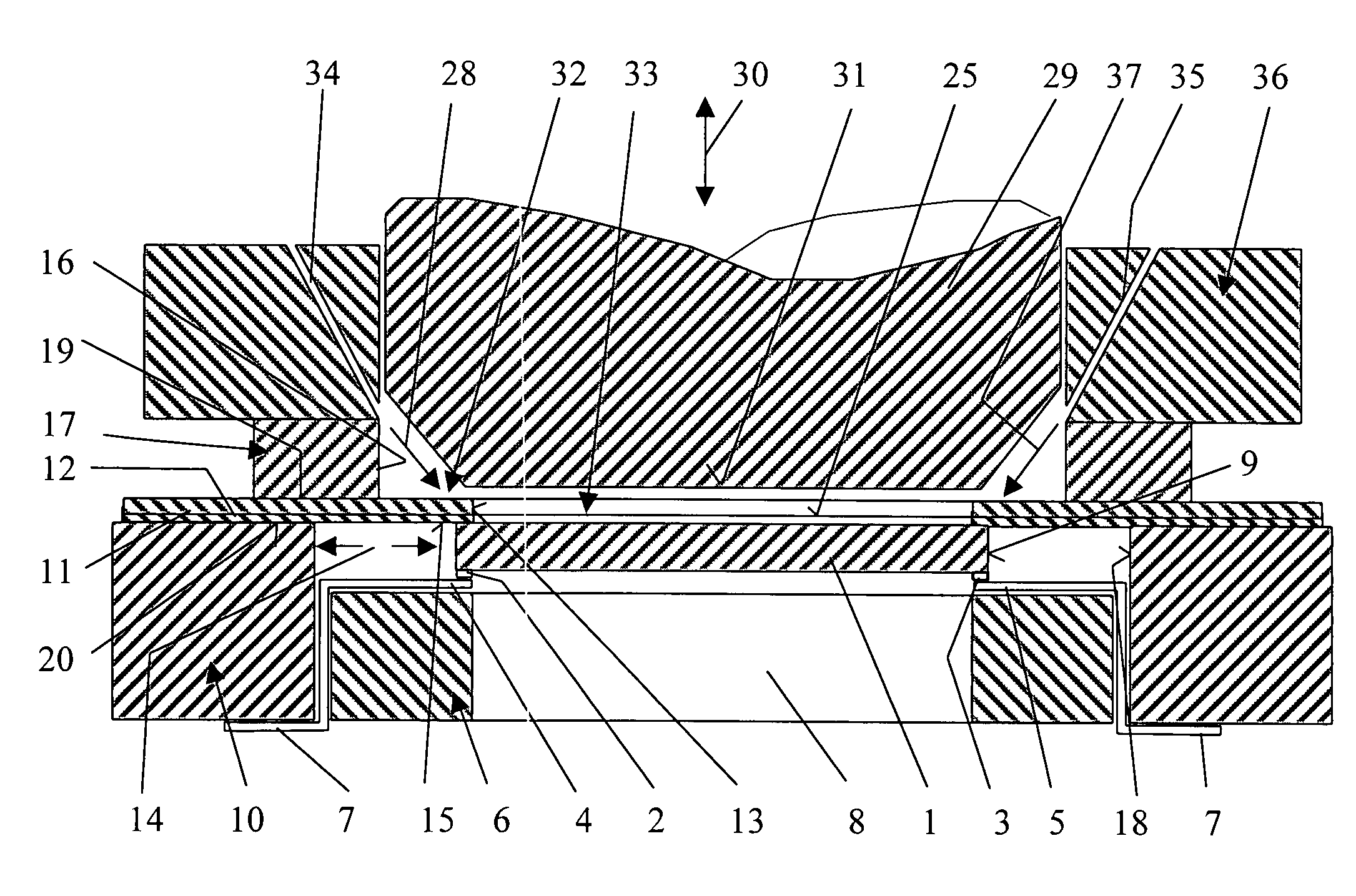
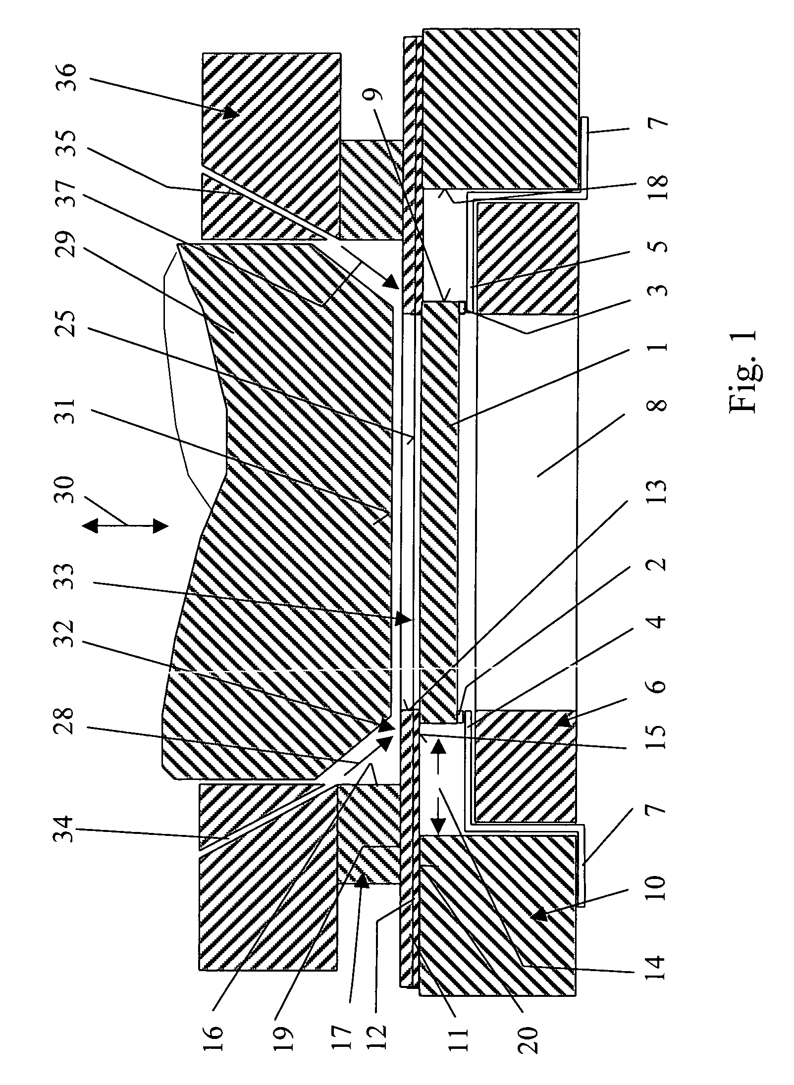
[0081]FIG. 1 shows an enlarged, schematic view of the lower part of a measurement chamber 36 according to FIGS. 7-11 and a measuring device, which is connected and sealed to the lower part of the measurement chamber 36.

[0082]The design of the measuring device is described in the following.

[0083]A disk-shaped resonator 1 (e.g., with the size of a 1-cent piece), serving as a disk-shaped oscillator, is supported in an inventive mounting.

[0084]At opposite points on its outside circumference, the resonator has two opposing contact surfaces 2, 3, which are very thin and which, in the exemplary embodiment according to FIG. 1, are shown with exaggerated thickness.

[0085]In reality, these contact surfaces 2, 3 are connected to the bottom surface of the resonator 1 in such a way that they are essentially flush with it.

[0086]The contact surfaces 2,3 of the resonator 1 rest with a precisely defined contact pressure on the opposing contact surfaces 4, 5 of a contact ring 6.

[0087]The contact ring ...


PUM

PropertyMeasurementUnit
thicknessaaaaaaaaaa
thicknessaaaaaaaaaa
thicknessaaaaaaaaaa

Abstract

The invention relates to an apparatus comprising a measurement chamber and a resonator, which can be integrated in the measurement chamber via a quick-action closure, for the liquid sensor system and for verification and measurement of the concentration of materials, substances, particles and/or microorganisms in liquids. The invention is characterized in that the resonator is held only on its outer circumference by a thin elastomer ring, and in that at the radial distance of the external diameter of the resonator, the elastomer ring on the one hand rests on an upper sealing ring of the measurement chamber, forming a seal, and on the other hand rests on a holding ring.

Description

[0001]This application claims priority to German Patent Application DE 10 2006 015 512.2 filed Mar. 31, 2006.FIELD OF THE INVENTION[0002]The invention pertains to a device consisting of a measurement chamber and a resonator.BACKGROUND OF THE INVENTION[0003]The object of DE 40 13 665 A1 is a sensor for the detection of a substance in a liquid. The sensor is designed as a resonator, which is integrated into a measurement chamber by means of a sealing device.[0004]One of the end surfaces of this resonator is in contact with the liquid to be tested. The substance in question, the presence of which is to be detected or the concentration of which is to be measured, accumulates on this end surface and thus leads to a change in the resonance frequency and / or in the vibration amplitude of the resonator. Differences in the properties of the liquid can also cause changes in these two measurement variables.[0005]The invention therefore pertains in particular to the area of piezoelectric quartz ...

Claims


Application Information

Patent Timeline
Patent Type & Authority Applications(United States)
IPC IPC(8): G01N29/036
CPCG01N29/022G01N29/036G01N29/222G01N2291/0422G01N2291/0224G01N2291/0255G01N2291/0256G01N2291/018
Inventor GEHRING, FRANK K.
Owner ANDREAS HETTICH GMBH & CO KG
Why Eureka
Try Eureka