
Separation of carbon nanotubes in density gradients

a carbon nanotube and density gradient technology, applied in the direction of optical radiation measurement, centrifugal force sediment separation, conductive materials, etc., can solve the problems of compromising the properties and utility of carbon nanotubes, and modifying the nanotubes

Active Publication Date: 2009-07-09
NORTHWESTERN UNIV
View PDF41 Cites 33 Cited by
  • Summary
  • Abstract
  • Description
  • Claims
  • Application Information

AI Technical Summary

Benefits of technology

The present invention provides methods and systems for separating carbon nanotubes based on their size and chirality. These methods and systems can be used in various production techniques and can be scaled for commercial use. They can also be used in conjunction with existing automation and scalability techniques. The separation techniques can involve using a density gradient in a fluid medium, which can separate the nanotubes based on their diameter or length. The invention also provides a method for separating single-walled carbon nanotubes by diameter. Overall, the invention provides new and improved methods for separating carbon nanotubes, which can be useful in various applications.

Problems solved by technology

However, such procedures chemically or structurally modify the nanotubes, at risk of compromising their properties and utility.

Method used


Image

  • Separation of carbon nanotubes in density gradients
  • Separation of carbon nanotubes in density gradients
  • Separation of carbon nanotubes in density gradients

Examples


example 1

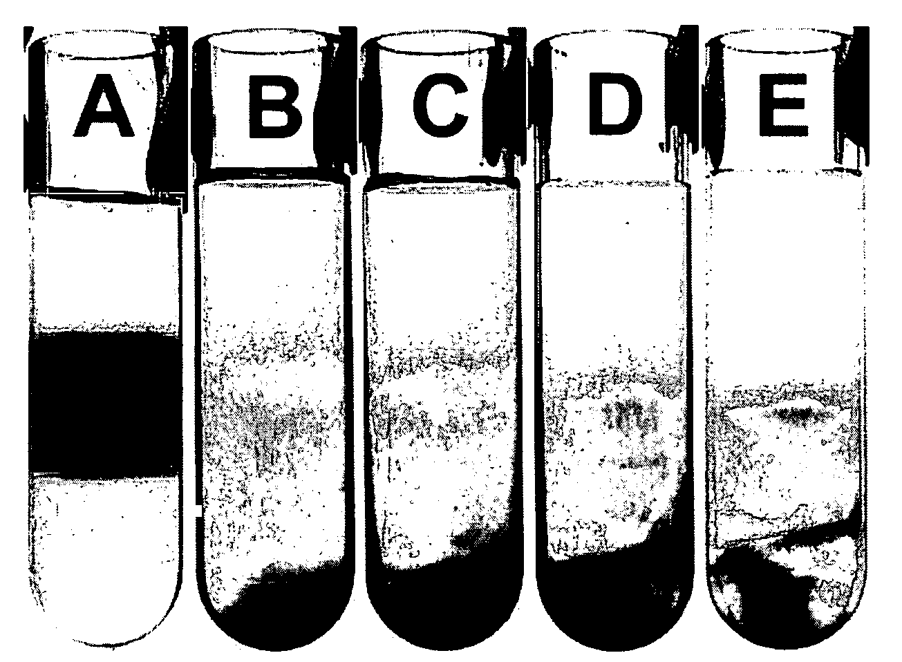
[0056]Isolation of SWNTs. In a modification of a known literature method, 1 mg of raw SWNTs was dispersed in aqueous solutions of 0.1 M NaCl and 1 mg mL−1 single-stranded DNA. (See, also Zheng; M., Jagota, A.; Strano, M. S; Santos, A. P.; Barone, P.; Chou, S. G., Diner, B. A; Dresselhaus, M. S.; McLean, R. S.; Onoa, G. B; Samsonidze, G. G.; Semke, E. D.; Usrey, M.; Walls, D. J. Science 2003, 302, 1545-1548, incorporated herein by reference in its entirety.) Raw SWNTs produced by the HiPCO and CoMoCAT methods were purchased from Carbon Nanotechnologies, Inc. and Southwest Nanotechnologies, Inc., respectively. Single-stranded DNA (GT)20 purified by standard desalting was purchased from Alpha DNA (Ontario, Canada). Aggregations and bundles of SWNTs were disrupted using a bath ultrasonicator (Model 3510, Branson) or a horn ultrasonicator coupled to a tapered extension, which was immersed into solution (Sonic Dismembrator 550, Fisher Scientific). Bath and horn ultrasonication times range...

example 2

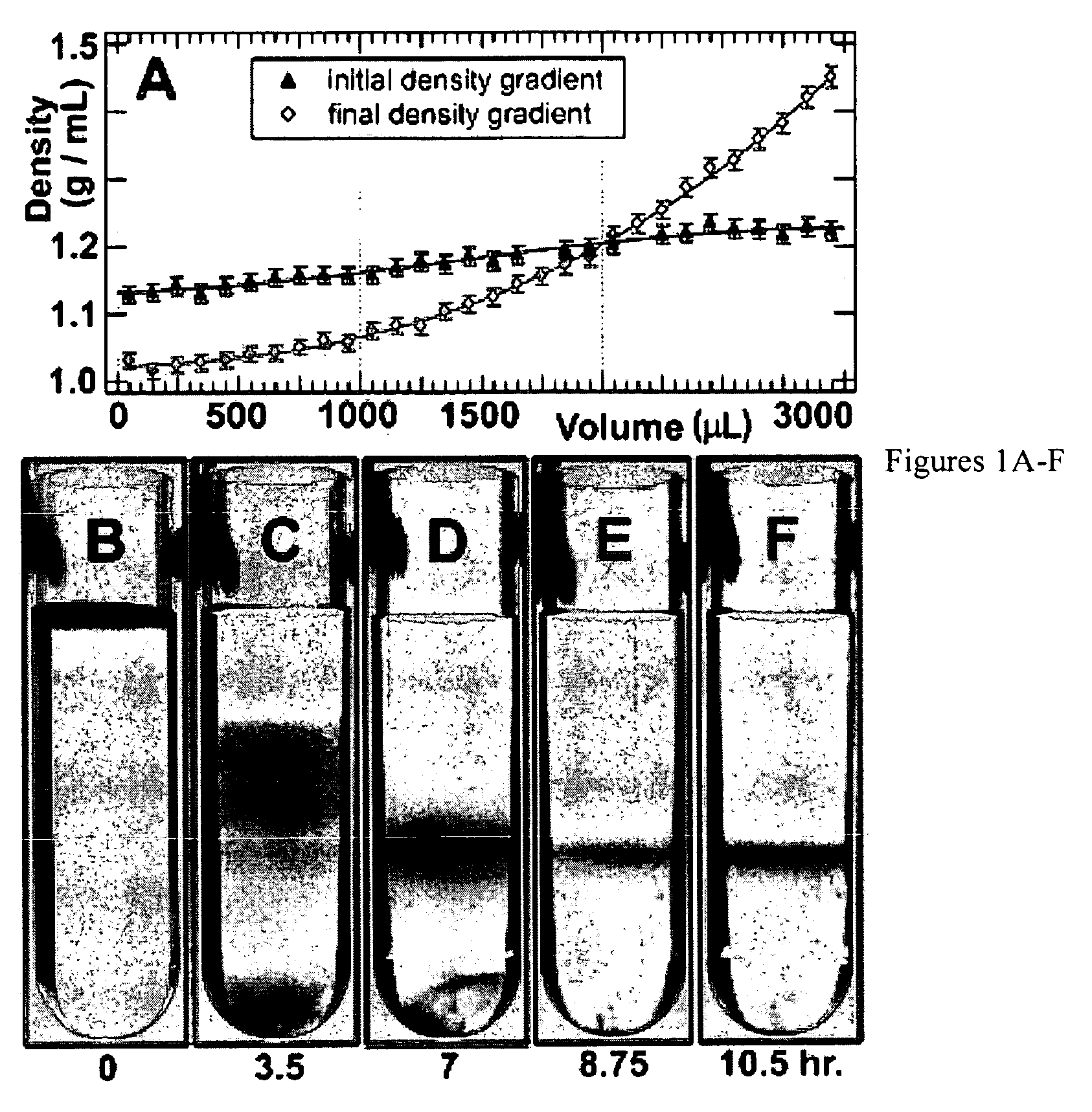
[0057]Diffusion of density gradients. After the layering the different iodixanol (FIG. 6) dilutions, the centrifuge tubes were tilted to ˜85 degrees for 60 minutes to enable an approximately linear gradient to form via diffusion.

example 3

[0058]Fractionation of density gradients. After ultracentrifugation, the gradients were fractionated by an upward displacement technique using a modified Beckman fraction recovery system. (J. M. Graham, Biological centrifugation (BIOS Scientific Publishers, Limited, ebrary, Inc., 2001), pp. 210) Fluorinert FC-40 (p˜1.85 g mL−1, Sigma-Aldrich, Inc.) was used as a water-immiscible displacement medium, which was introduced to the bottom of the centrifuge tube by a motor controlled syringe pump (PHD 2000, Harvard Apparatus, Inc.) at a speed of 0.5 mL min−1 through a 22-gauge stainless-steel tube in steps of 25 or 100 μL. To measure the density profile of a density gradient, 100 μL fractions were collected, and the density of each fraction was measured within an error ±1% by massing a known volume of each fraction using a calibrated micro-pipette and an electronic balance. To measure the optical absorbance spectra of SWNTs in a density gradient as a function of position in the gradient, ...


PUM

PropertyMeasurementUnit
densitiesaaaaaaaaaa
pHaaaaaaaaaa
lengthaaaaaaaaaa

Abstract

The separation of single-walled carbon nanotubes (SWNTs), by chirality and / or diameter, using centrifugation of compositions of SWNTs in and surface active components in density gradient media.

Description

[0001]This application claims priority benefit from prior provisional application Ser. No. 60 / 658,502, filed Mar. 4, 2005, the entirety of which is incorporated herein by reference.[0002]The United States government has certain rights to this invention pursuant to Grant Nos. DMR-0134706 and EEC-0118025 from the National Science Foundation and Grant No. DE-FG02-00ER45810 / A001 from the Department of Energy, all to Northwestern University.BACKGROUND OF THE INVENTION[0003]The utilization of single-walled carbon nanotubes (SWNTs) in large quantities in the fields of molecular electronics, opto-electronics, and biological sensing will require SWNTs of the same physical structure, electronic-type, and band gap. Since current methods of synthesis produce mixtures of nanotubes with different physical structures and electrical properties, the development of methods for the post-production separation of these one-dimensional materials is necessary. Towards this end, progress has been reported ...

Claims


Application Information

Patent Timeline
Patent Type & Authority Applications(United States)
IPC IPC(8): D01F9/12B32B5/02H01B1/04G01J3/42
CPCB82Y30/00B82Y40/00C01B31/0233C01B31/0266C01B2202/02Y10T428/2918C01B2202/36Y10S977/75Y10S977/845Y10T436/25375C01B2202/34C01B32/162C01B32/172B82B3/00B82Y5/00
Inventor HERSAM, MARK C.STUPP, SAMUEL I.ARNOLD, MICHAEL S.
Owner NORTHWESTERN UNIV
Learn More