
Method and Device for Forming a Signature

a signature and method technology, applied in the field of methods and devices for forming signatures, can solve the problems of data elements that cannot be transmitted until, and are computationally and time-consuming, and achieve the effect of freeing up resources for other tasks and speeding up the formation of additional signatures

Inactive Publication Date: 2009-07-09
ROBERT BOSCH GMBH
View PDF1 Cites 1 Cited by
  • Summary
  • Abstract
  • Description
  • Claims
  • Application Information

AI Technical Summary

Benefits of technology

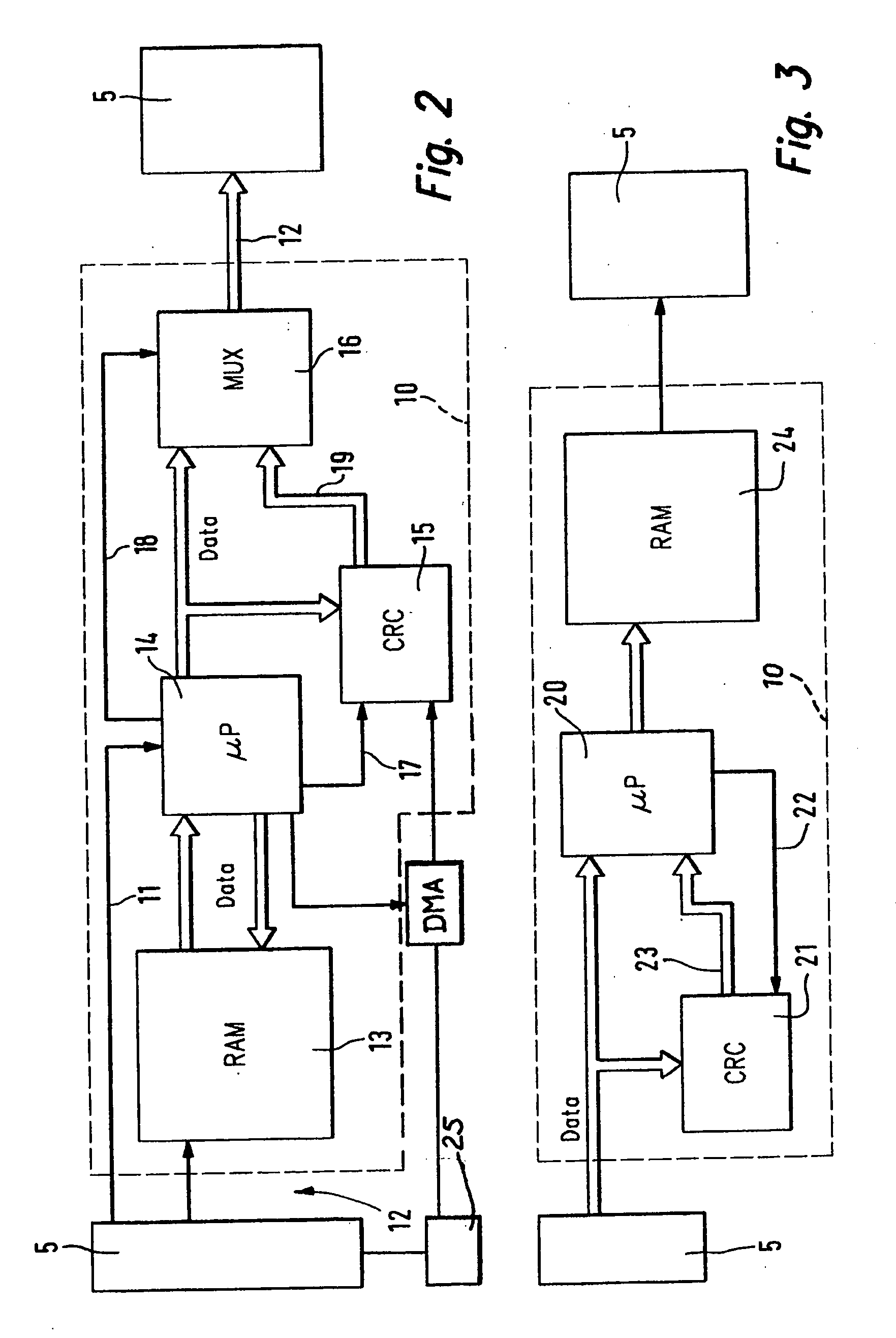
[0006]Example embodiments of the present invention may speed up the formation of the additional signature and thus the data transfer between the computer unit (the microcontroller) and the communication controller of the transmitter unit or of the receiver unit and / or to relieve the computer unit (microcontroller) from this task and thus free resources for other tasks.
[0010]According to example embodiments of the present invention, the extensive task of having to regularly form a signature is removed from the arithmetic unit. In addition, a signature formation device implemented in the hardware may be implemented using considerably less complexity and in a substantially simpler manner than would be possible with the aid of software. The hardware for signature formation may be monitored for proper operation without problems. The hardware may be used either for monitoring the communication path within a communication system or for securing any other data within the communication system. The hardware for signature formation offers the possibility to monitor an interface (for example, an SPI (Serial Peripheral Interface) bus) that would be difficult to monitor otherwise.

Problems solved by technology

This additional signature is formed and analyzed in the software running on the arithmetic unit of the transmitter unit or of the receiver unit of the communication system and is very resource-intensive, i.e., computing- and time-intensive.
Due to the typically bit-by-bit signature formation in the software, a data element, however, may not be transmitted until all bits of the data element have been involved in the signature formation, i.e., after a plurality of computer cycles has elapsed.
In that case, signature formation may represent a true bottleneck because the communication requires considerably fewer computer cycles than conventional signature formation by the software.

Method used


Image

  • Method and Device for Forming a Signature
  • Method and Device for Forming a Signature
  • Method and Device for Forming a Signature

Examples


Embodiment Construction

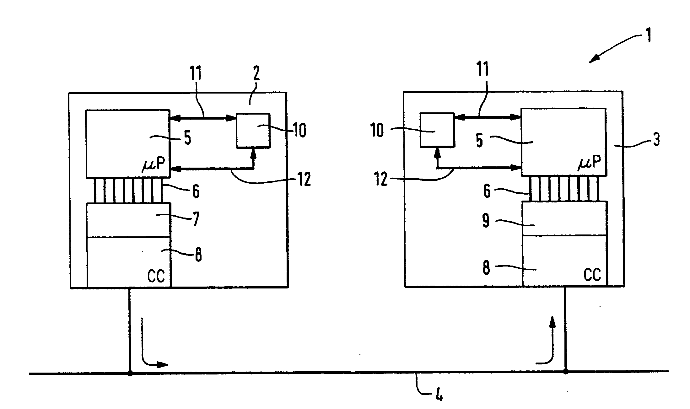
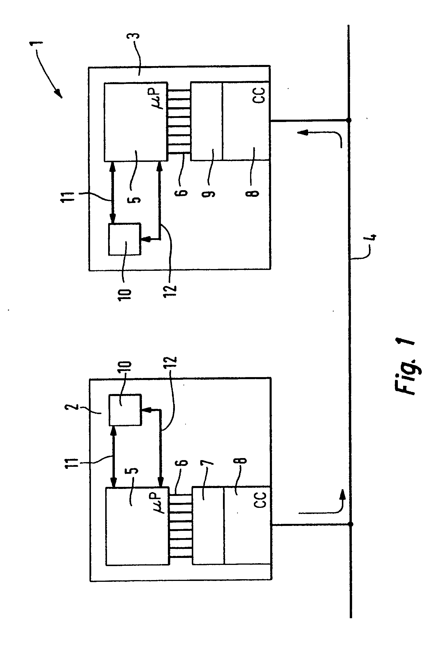
[0022]In FIG. 1, a communication system according to an example embodiment of the present invention is labeled with reference numeral 1. The communication system includes two users, one transmitter unit 2 and one receiver unit 3. Data may be exchanged between transmitter unit 2 and receiver unit 3 via a communication medium 4, which is arranged as a data bus, for example. Each of users 2, 3 includes an arithmetic unit 5, which is arranged, for example, as a microprocessor and is also referred to as a Central Processing Unit (CPU). Arithmetic unit 5 of transmitter unit 2 transfers data, which are to be transmitted to receiver unit 3 via communication medium 4, to an output buffer 7 of a communication controller 8 via a plurality of parallel lines 6, e.g., via eight lines. Communication controller 8 of receiver unit 3 transfers the data received from communication medium 4 to arithmetic unit 5 via an input buffer 9 and parallel lines 6 for further processing.

[0023]The data to be trans...


PUM


Abstract

A device and a method are for forming a signature for use in a transmitter unit or a receiver unit of a communication system. To speed up the formation of a signature and thus the data transfer between a computer unit (e.g., a microcontroller) and a communication controller of the transmitter unit or the receiver unit, the device is arranged as hardware and the device forms the signature for data which are to be transferred from a computer unit of the transmitter unit to a communication controller of the transmitter unit for the purpose of data transmission via a communication medium of the communication system or which are to be transferred from a communication controller of the receiver unit to a computer unit of the receiver unit for further processing.

Description

FIELD OF THE INVENTION[0001]The present invention relates to a method and a device for forming a signature for use in a transmitter unit or a receiver unit of a communication system.[0002]In addition, the present invention relates to a transmitter unit of a communication system including a computer unit and a communication controller through which the transmitter unit is connected to a communication medium. The transmitter unit has a device for forming a signature for data which are to be transferred from the computer unit to the communication controller for the purpose of transmission via the communication medium.[0003]The present invention also relates to a receiver unit of a communication system including a computer unit and a communication controller through which the receiver unit is connected to a communication medium. The receiver unit has a device for forming a signature for data which are to be transmitted to the communication controller via the communication medium and whi...

Claims


Application Information

Patent Timeline
Patent Type & Authority Applications(United States)
IPC IPC(8): G06F1/00H04L9/32H04L1/00
CPCB60W50/00B60W50/0098H04L2209/12H04L9/3247H04L9/06
Inventor MUELLER, BERNDHARTER, WERNERBOEHL, EBERHARDHAEFNER, THOMASHAEFNER, GERHARDHAEFNER, RENATEKOTTKE, THOMASVON COLLANI, YORCK
Owner ROBERT BOSCH GMBH
Learn More