Arrangement of a semiconductor-type igniter plug in a gas turbine engine combustion chamber

a technology of semiconductor-type igniter and combustion chamber, which is applied in the direction of machine/engine, burner ignition device, lighting and heating apparatus, etc., can solve the problems of difficult reconciliation, adverse effect on the thermal integrity of these components, and reduce the ease of ignition within the chamber, so as to improve the longevity of semiconductor-type igniter plugs and limit the impingement of fuel thereon.

Active Publication Date: 2009-07-16
SN DETUDE & DE CONSTR DE MOTEURS DAVIATION S N E C M A
View PDF5 Cites 25 Cited by
  • Summary
  • Abstract
  • Description
  • Claims
  • Application Information

AI Technical Summary

Benefits of technology

[0009]It is an object of the present invention to improve the longevity of semiconductor-type igniter plugs by proposing a new igniter plug arrangement that allows the semiconductor to be cooled while at the same time limiting the impingement of fuel thereon.

Problems solved by technology

These two conditions dictate arrangements that are difficult to reconcile.
If this angle is very tight, the igniter plug is outside of the cone formed by the fuel, which is favorable in terms of thermal integrity but reduces the ease of ignition within the chamber.
This has an adverse effect on the thermal integrity of these components.
The life of the igniter plugs is limited; in the case of “high energy / high voltage” igniter plugs, this is limited by electrode wear and in the case of “high energy / low voltage” igniter plugs, life is limited by semiconductor wear, the semiconductor becoming worn away more rapidly than the electrodes.
After repeated ignition sequences, the igniter plug semiconductor experiences significant thermal stresses.
The impingement of fuel on the semiconductor, together with the electric arc cause damage to this semiconductor, altering its shape.

Method used


Image

  • Arrangement of a semiconductor-type igniter plug in a gas turbine engine combustion chamber
  • Arrangement of a semiconductor-type igniter plug in a gas turbine engine combustion chamber

Examples


Embodiment Construction

)

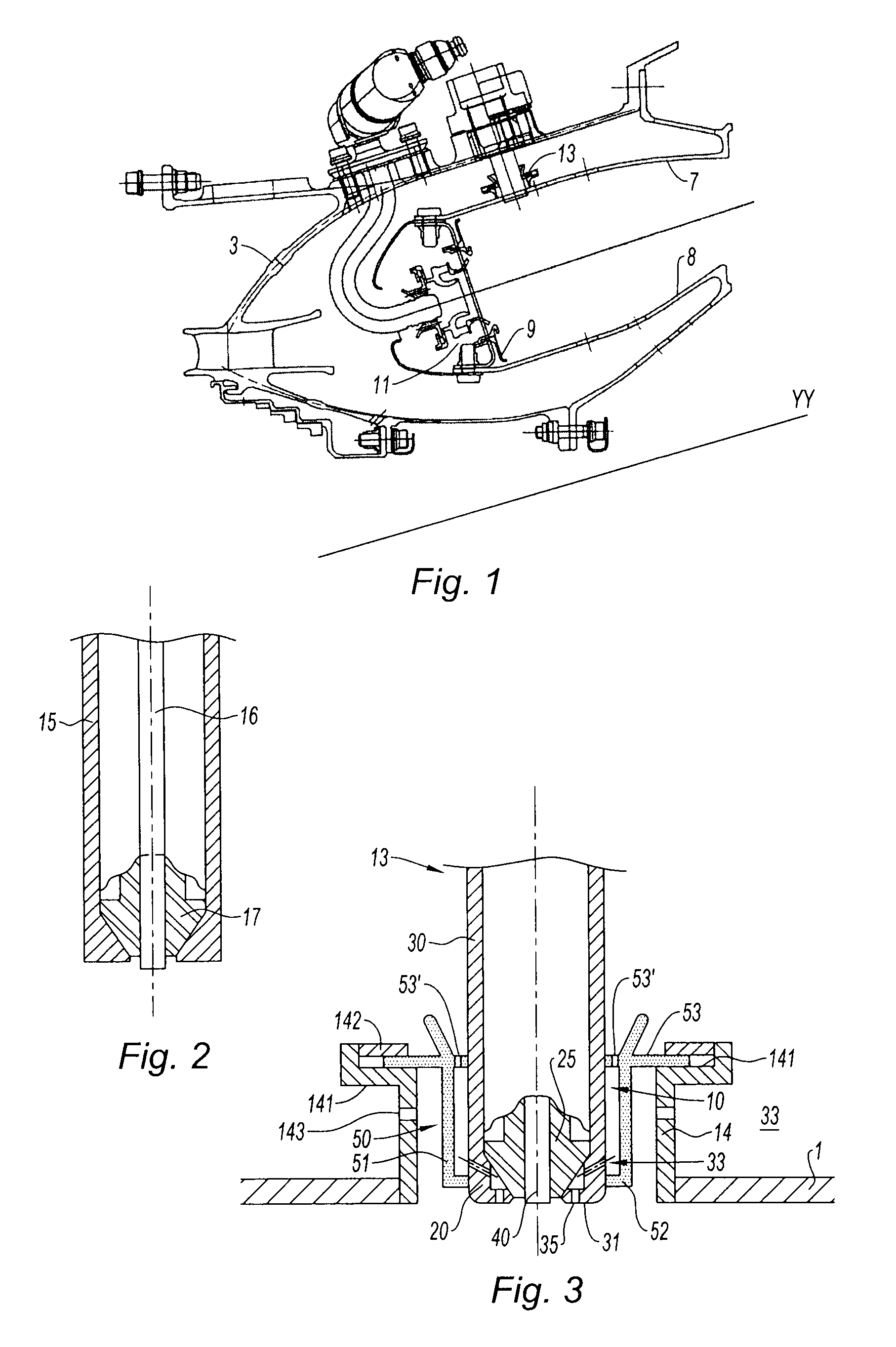
[0020]As may be seen in FIG. 1, the combustion chamber I is contained in an annular space formed by an external casing 3. It comprises one or more outer shell rings 7 with flanges or supports, one or more internal shell rings 8 with flanges, a chamber end wall 9 associated with upstream fairings. A plurality of fuel injection pipes, distributed about the axis of the engine, opens into the chamber end wall 9. Deflectors 11 form a bowl around each supply pipe, deflect some of the air that has entered the faired zone in a radial and swirling direction toward the atomized fuel, and thus create a mixture of fuel with air. A primary combustion zone is formed downstream of the chamber end wall and it is here that the mixture is ignited by one or more circumferentially distributed igniter plug(s) 13.

[0021]FIG. 2 is a schematic diagram of the basic design of a semiconductor-type igniter plug. This is made up of a tubular metal body that constitutes the shell or external electrode 15 of the ...


PUM


Abstract

The present invention relates to an arrangement comprising an igniter plug of the semiconductor in shell type, a duct secured to a combustion chamber of a gas turbine engine, a floating sleeve via which the igniter plug is mounted in the duct, in order to accommodate expansion along an axis perpendicular to the axis of the igniter plug. It notably comprises means for guiding air to cool the semiconductor of the igniter plug, the shell and the semiconductor defining, at their combustion-chamber end, an annular igniter plug cavity, and the shell comprising orifices in the region of the igniter plug annular cavity that communicate with the annular cavity of the sleeve and orifices on its planar surface.

Description

BACKGROUND OF THE INVENTION AND DESCRIPTION OF THE PRIOR ART[0001]The present invention relates to the field of gas turbine engines and is concerned more specifically with the arrangement of a semiconductor-type igniter plug mounted in a combustion chamber.[0002]In a gas turbine engine, the combustion chamber receives air from the compressor, some of which air is mixed with the fuel which is burnt in the primary combustion zone. Ignition is brought about by one or two igniter plugs positioned downstream of the carburetion system. Another part of the air bypasses the primary combustion zone and mixes with the combustion gases. All of the hot gases are directed toward the turbine. The combustion chambers are designed to meet a certain number of essential specifications such as: in-flight reignition, the shape of the temperature profile, the emissions of pollutant gases and both thermal and mechanical integrity of the various components thereof.[0003]In particular, the ignition system ...

Claims


Application Information

Patent Timeline
Patent Type & Authority Applications(United States)
IPC IPC(8): F02C7/266
CPCF02C7/266F23D2207/00F05D2260/20F23R3/002F23R2900/00012F23D2214/00
Inventor SANDELIS, DENIS JEAN MAURICE
Owner SN DETUDE & DE CONSTR DE MOTEURS DAVIATION S N E C M A
Why Eureka
Try Eureka