Control of materials and porous magnetic particles

a technology of porous magnetic particles and control of materials, applied in the field of micro-processes, can solve the problems of limiting the rate at which samples can be heated and cooled, micro-scale quantities of materials that have to be controlled, and the problem of advanced droplet-based microfluidics is particularly problemati

Inactive Publication Date: 2009-07-16
RGT UNIV OF CALIFORNIA
View PDF13 Cites 18 Cited by
  • Summary
  • Abstract
  • Description
  • Claims
  • Application Information

AI Technical Summary

Benefits of technology

[0012]The present invention uses externally applied electromagnetic stimulus to control and heat porous magnetic particles and material associated with the particles. The particles contain magnetic material, such as super paramagnetic iron oxide and are associated with a material to be controlled. Application of a DC magnetic field allows them to be moved with their associated material, and application of an AC RF electromagnetic field allows them to be heated with their associated material. The material can be associated with the particles by being contained in the pores of the particles, or in other cases the particles can adhere to the associated material, which can be an aqueous droplet.

Problems solved by technology

Chemical and biological processes such as enzymatic assays, protein identification, and combinatorial synthesis, for example, present the problem of having microscale quantities of material that have to be controlled.
The primary restrictions associated with these heating methods are the thermal properties and mass of the heating block and the reaction chamber, which ultimately limit the rate at which the sample can be heated and cooled.
Advanced droplet-based microfluidics is especially problematic due to the required efficient localized heating of the individual droplets with minimal heat transfer to the surroundings.

Method used


Image

  • Control of materials and porous magnetic particles
  • Control of materials and porous magnetic particles
  • Control of materials and porous magnetic particles

Examples


specific example embodiments

Experiments and Specific Example Embodiments

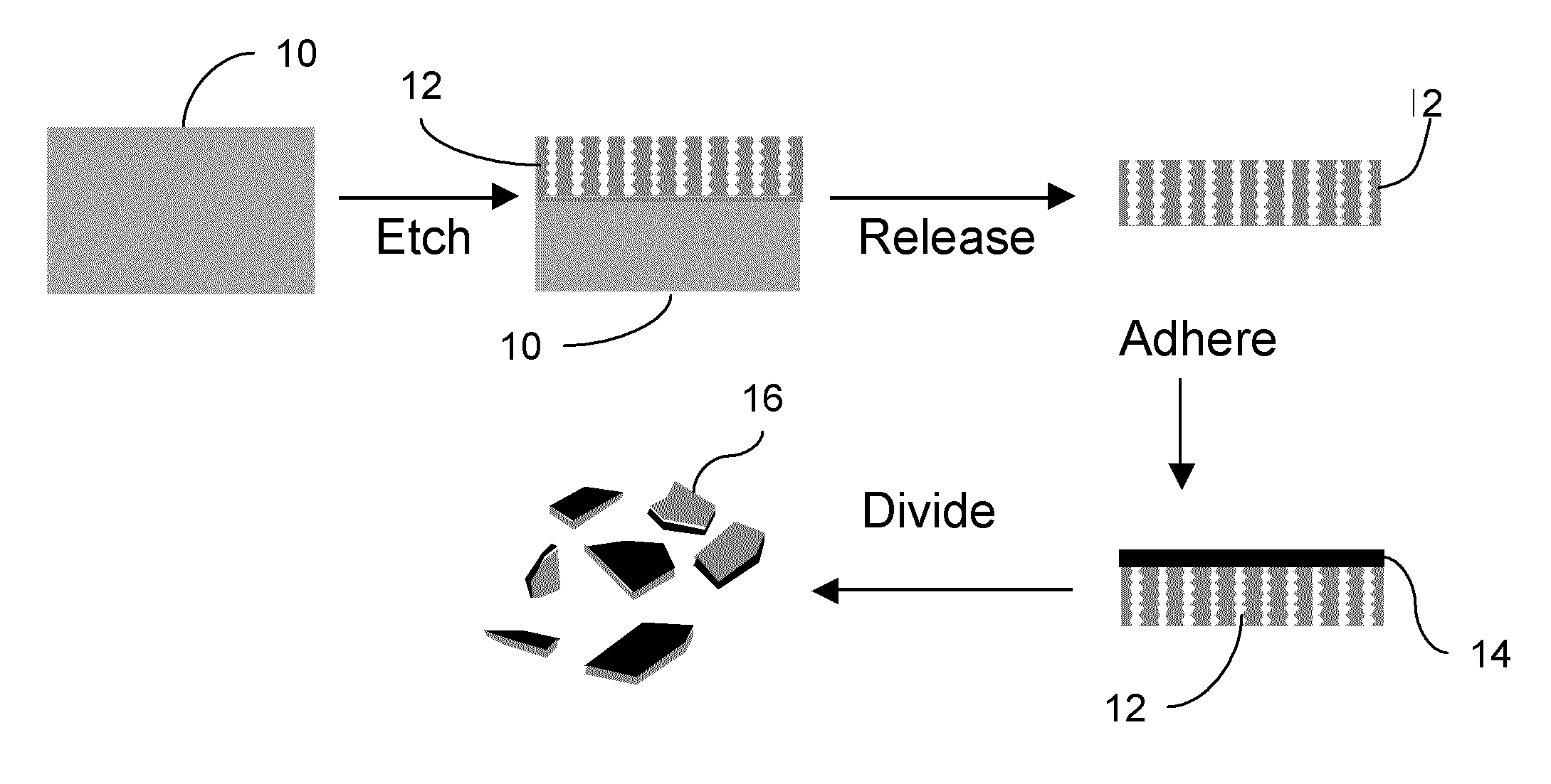
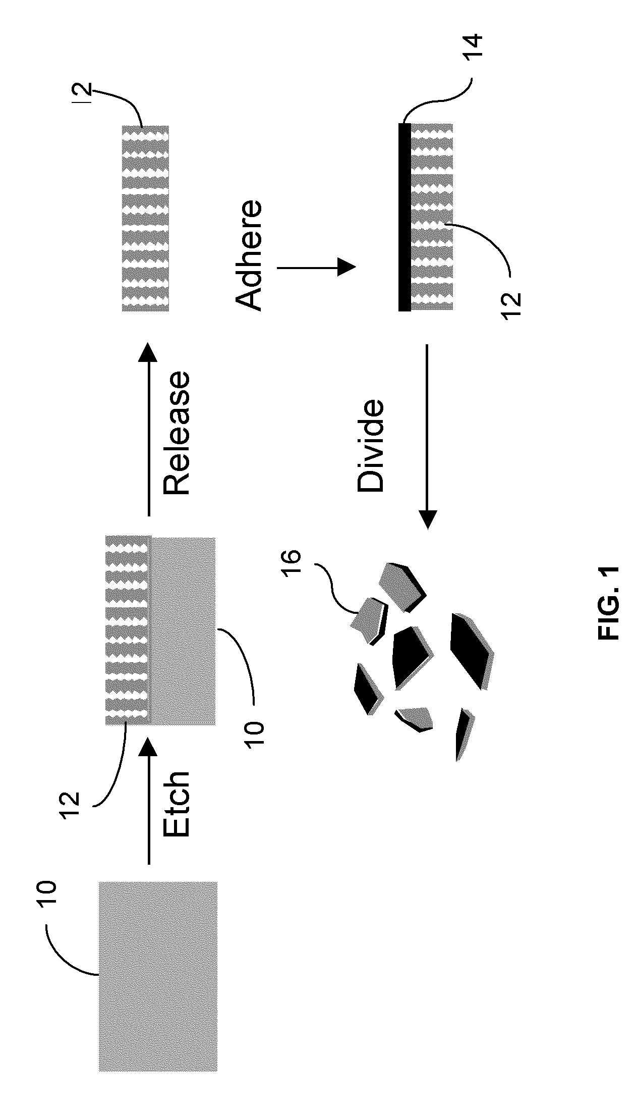
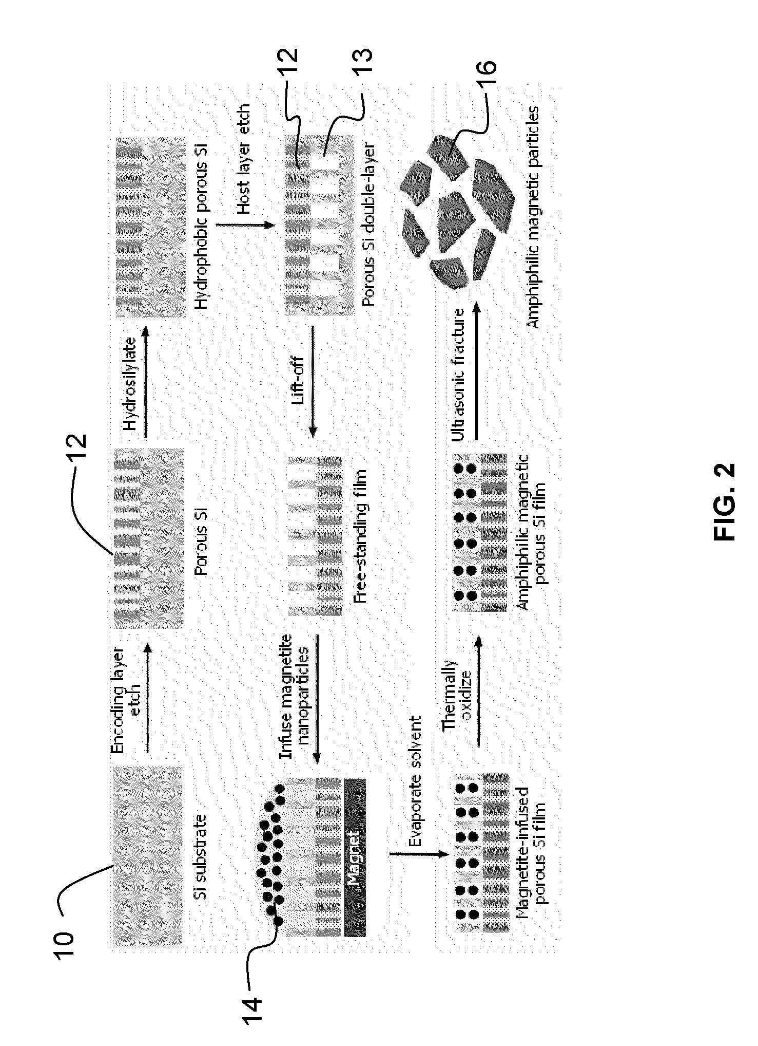
[0062]A magnetite (Fe3O4) colloidal suspension with a mean particle size of 10 nm (measured by Transmission Electron Microscopy) was prepared The magnetite suspension was mixed with acetone at a ratio of 1:3 (v / v). The concentration of the final magnetite suspension was approx. 1 mg / mL. A porous Si film (with its host layer side facing up) was placed in the center of an aluminum weighing dish and a strong magnet was located under the dish. A volume of 0.5 mL of the magnetite nanoparticle suspension was added on top of the film. When the solution evaporated, the magnetized film was rinsed thoroughly with ethanol and acetone several times and then dried in air. The film was then thermally oxidized at 100° C. overnight. The thermally oxidized film was fractured to micron-sized particles by ultrasonication (20 s) in acetone. The resulting magnetic porous Si microparticles were rinsed with ethanol and acetone several times and then filtered usi...


PUM

PropertyMeasurementUnit
temperaturesaaaaaaaaaa
particle sizeaaaaaaaaaa
volumeaaaaaaaaaa

Abstract

The present invention uses externally applied electromagnetic stimulus to control and heat porous magnetic particles and material associated with the particles. The particles contain magnetic material, such as superparamagnetic iron oxide and are associated with a material. Application of a DC magnetic field allows them to be moved with their associated material, and application of an AC RF electromagnetic field allows them to be heated with their associated material. The material can be associated with the particles by being contained in the pores of the particles, or in other cases the particles can adhere to the associated material, which can be an aqueous droplet. The present invention also provides a multi-layer porous magnetic particle. The particle includes a host layer having pores sized to accept magnetic nanoparticles. Magnetic nanoparticles are infused within pores of the host layer An encoding layer includes pores that define a spectral code. The pores in the encoding layer are sized to substantially exclude the magnetic nanoparticles. The encoding layer can also be a multi-layer, exhibiting, for example, a complex spectral code.

Description

CLAIMS FOR PRIORITY[0001]This application claims priority pursuant to 35 U.S.C. §119 from prior provisional application Ser. No. 60 / 800,950 filed May 17, 2006, and entitled Droplet Control with Porous Particles. This application claims priority pursuant to 35 U.S.C. § 120 and is a continuation in part of pending application Ser. No. 11 / 632,914, filed Jan. 18, 2007 based upon PCT / US2005 / 025383 filed Jul. 18, 2005, and entitled Magnetic Porous Particles and Method of Making, which claimed priority from provisional application Ser. No. 60 / 589,171, which was filed on Jul. 19, 2004.STATEMENT OF GOVERNMENT INTEREST[0002]This invention was made with government support under AFOSR Contract No. F49620-02-1-0288 and NIH Contract Nos. 1U54CA119335 & NO1-CO-37117. The government has certain rights in the inventionFIELD[0003]A field of the invention is microscale processes. The invention concerns control, such as manipulation and heating, of microscale quantities of materials. The invention can ...

Claims


Application Information

Patent Timeline
Patent Type & Authority Applications(United States)
IPC IPC(8): H01F1/00H05B6/02
CPCB82Y25/00H01F1/0063H05B6/02Y10T428/2982Y10T428/29Y10T428/2991Y10T428/32
Inventor SAILOR, MICHAEL J.PARK, JI-HODERFUS, AUSTIN M.SEGAL, ESTERVECCHIO, KENNETH S.BHATIA, SANGEETA N.
Owner RGT UNIV OF CALIFORNIA
Why Eureka
Try Eureka