Overcurrent protection circuit and voltage regulator incorporating same

a voltage regulator and overcurrent protection technology, applied in the direction of electric variable regulation, electrical equipment, instruments, etc., can solve the problems of system or load deriving power from the voltage regulator not being informed, reducing the output voltage vout, and reducing the current passed. , to achieve the effect of reducing the current passed

Inactive Publication Date: 2009-07-16
RICOH ELECTRONIC DEVICES CO LTD
View PDF4 Cites 16 Cited by
  • Summary
  • Abstract
  • Description
  • Claims
  • Application Information

AI Technical Summary

Benefits of technology

[0018]In one aspect of the present disclosure, a novel constant voltage regulator includes an output transistor, a control circuit, and an overcurrent protection circuit. The output transistor is configured to regulate a voltage input to an input terminal to output a given constant voltage to an output terminal, while passing a current from the input terminal to the output terminal according to a control signal applied thereto. The control circuit is configured to generate the control signal so that a voltage proportional to the output voltage matches a given reference voltage. The overcurrent protection circuit is configured to prevent excessive current flow in the constant voltage regulator, and includes a current limiter and a status detector. The current limiter reduces the current passed through the output transistor when the passed current exceeds a given current limit. The status detector is configured, to generate a status signal indicating operation of the current limiter.

Problems solved by technology

Such overcurrent occurrence and subsequent current limitation is accompanied by a reduction in the output voltage Vout.
Such current limitation is also seen in certain constant power supplies incorporating a foldback current limiter, another typical form of overcurrent protection circuit.
One drawback of the technique depicted in FIG. 1 is that a system or load deriving power from the voltage regulator is not informed of operating status of the overcurrent protection circuit.
In particular, monitoring current limitation where the output voltage changes with the output current is difficult, since the current limit can oscillate as the output voltage rapidly changes in response to changes in the limited output current.
Such failure to relay and monitor the operating status of the overcurrent protection circuit makes it difficult to diagnose malfunctions in the system powered by the overcurrent-protected voltage regulator.

Method used


Image

  • Overcurrent protection circuit and voltage regulator incorporating same
  • Overcurrent protection circuit and voltage regulator incorporating same
  • Overcurrent protection circuit and voltage regulator incorporating same

Examples


Embodiment Construction

[0025]In describing exemplary embodiments illustrated in the drawings, specific terminology is employed for the sake of clarity. However, the disclosure of this patent specification is not intended to be limited to the specific terminology so selected, and it is to be understood that each specific element includes all technical equivalents that operate in a similar manner and achieve a similar result.

[0026]Referring now to the drawings, wherein like reference numerals designate identical or corresponding parts throughout the several views, examples and exemplary embodiments of this disclosure are described.

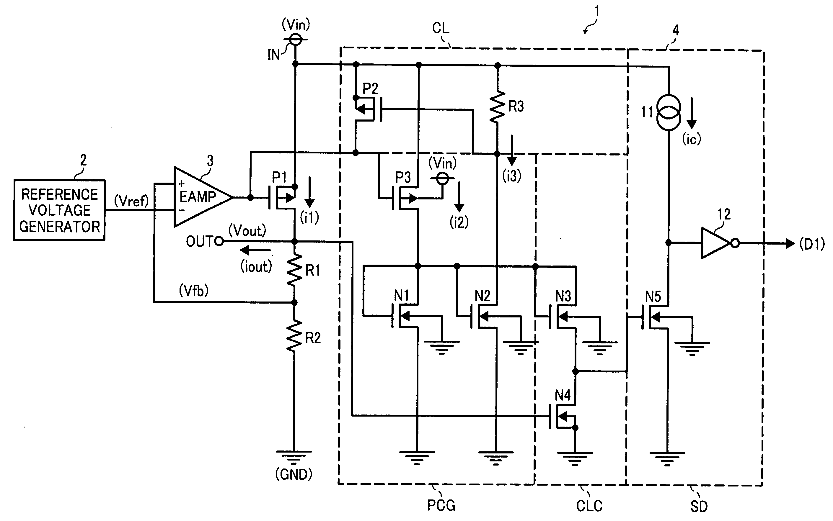
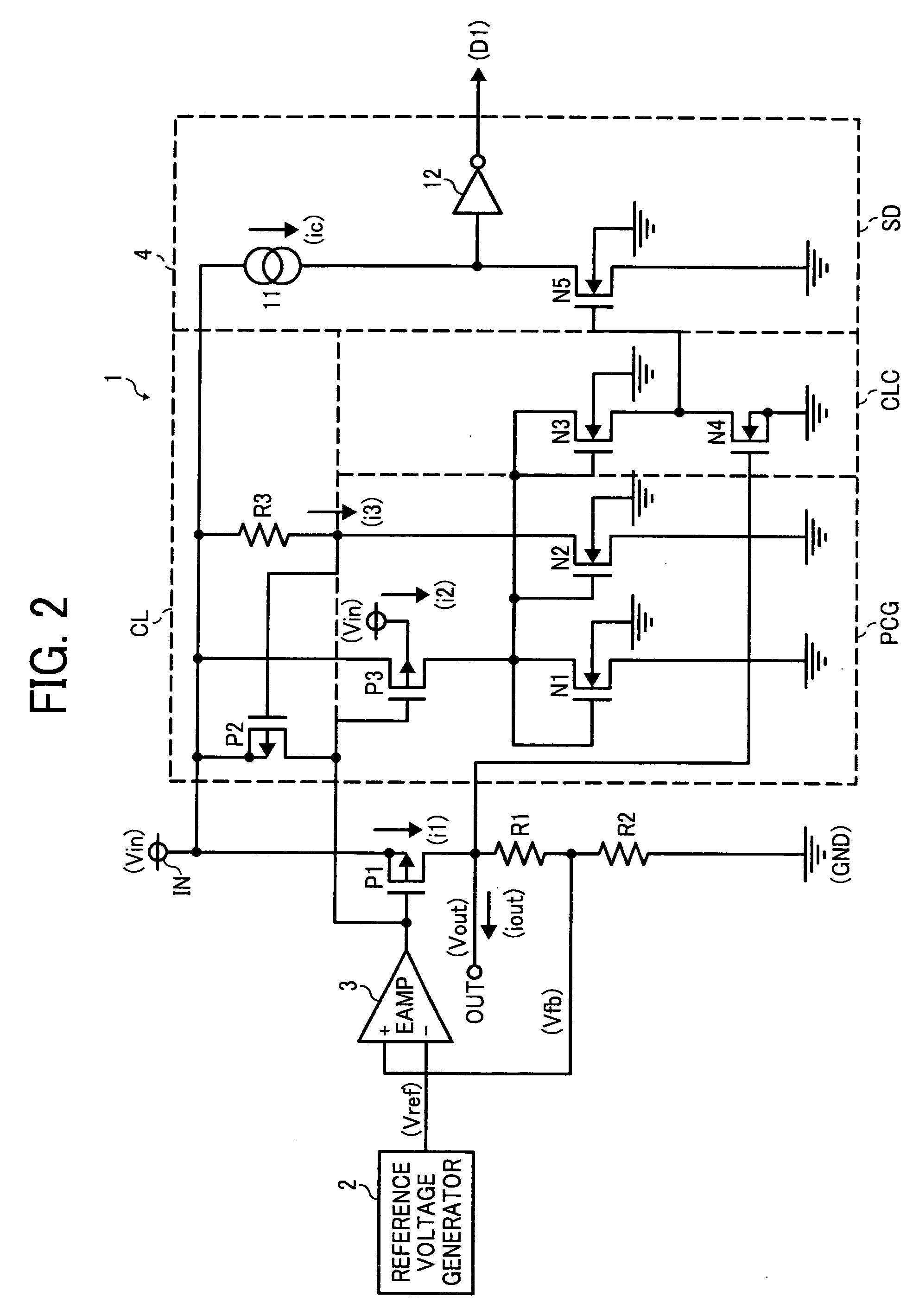
[0027]FIG. 2 is a circuit diagram illustrating a constant voltage regulator 1 incorporating an overcurrent protection circuit 4 according to one embodiment of this patent specification.

[0028]As shown in FIG. 2, the voltage regulator 1 includes a P-channel metal-oxide-semiconductor (PMOS) transistor P1, resistors R1 and R2, a reference voltage generator 2, and an error amplifier 3,...


PUM


Abstract

An overcurrent protection circuit includes a current limiter and a status detector, and a voltage regulator includes an output transistor. The output transistor is configured to regulate a voltage input to an input terminal to output a given constant voltage from an output terminal, while passing a current from the input terminal to the output terminal according to a control signal applied thereto. The current limiter reduces the current passed through the output transistor when the passed current exceeds a given current limit. The status detector is configured to generate a status signal indicating operation of the current limiter. A constant voltage regulator incorporating the overcurrent protection circuit is also disclosed.

Description

BACKGROUND OF THE INVENTION[0001]1. Technical Field[0002]The present invention relates to an overcurrent protection circuit and a voltage regulator incorporating the same, and more particularly, to an overcurrent protection circuit that prevents excessive current in a constant voltage regulator supplying constant power to electronic equipment, and a voltage regulator incorporating such an overcurrent protection circuit.[0003]2. Discussion of the Background[0004]Overcurrent protection circuits are employed in power supplies to protect electronic components from excessive current. One typical application of overcurrent protection is in a constant voltage regulator, which limits current flow in an active component and load circuitry used therewith.[0005]FIG. 1 is a circuit diagram illustrating a constant voltage regulator 100 incorporating a conventional overcurrent protection circuit.[0006]As shown in FIG. 1, the voltage regulator 100 includes a main circuit formed of a P-channel meta...

Claims


Application Information

Patent Timeline
Patent Type & Authority Applications(United States)
IPC IPC(8): H02H9/02
CPCG05F1/573
Inventor TANAKA, SHUNSEI
Owner RICOH ELECTRONIC DEVICES CO LTD
Why Eureka
Try Eureka