Processing apparatus and process method

a processing apparatus and processing method technology, applied in the field of processing apparatus and processing method, can solve the problems of shortened cleaning cycle, unnecessary adhesive coating, and considerable increase in energy consumption of heating the processing vessel, so as to improve the in-plane temperature uniformity of the object, save energy consumption, and improve the effect of in-plane temperatur

Inactive Publication Date: 2009-07-23
TOKYO ELECTRON LTD
View PDF11 Cites 13 Cited by
  • Summary
  • Abstract
  • Description
  • Claims
  • Application Information

AI Technical Summary

Benefits of technology

[0065]According to the processing apparatus and the processing method of the present invention, the following excellent effect can be provided.
[0067]Accordingly, as described above, an object to be processed can be heated without heating a processing vessel itself with the use of induction heating, whereby an energy consumption can be saved, an unnecessary adhesive coat or the like is prevented from being deposited on an inner surface of the processing vessel, and a temperature of the object to be processed can be rapidly increased and decreased.
[0068]Furthermore, since the induction heating element is provided with the cut groove for controlling a flow of an eddy current generated on the induction heating element, the eddy current can flow over all the surface of the induction heating element. Thus, it is possible to improve an in-plane-temperature uniformity of the object to be processed that is heated by the induction heating element.

Problems solved by technology

Thus, there is a problem in that an energy consumption is considerably increased for heating the processing vessel 2.
In addition, since the processing vessel 2 itself is exposed to a high temperature, when a film deposition process is performed, for example, unnecessary adhesive coats are likely to deposit not only on the surfaces of the wafers W of a high temperature but also on an inside wall surface of the processing vessel 2 heated at a high temperature.
Thus, there are other problems in that the unnecessary adhesive coats cause particles, and that a cleaning cycle is shortened because of the unnecessary adhesive coats.
Thus, there is a further problem in that it is significantly difficult to rapidly increase and decrease the temperature of the wafer W.

Method used


Image

  • Processing apparatus and process method
  • Processing apparatus and process method
  • Processing apparatus and process method

Examples


second embodiment

of Processing Apparatus

[0184]Next, a processing apparatus in a second embodiment of the present invention is described below. FIG. 15 is a perspective view showing a processing apparatus in a second embodiment of the present invention. FIG. 16 is a schematic view showing an appearance of the processing apparatus in the second embodiment. FIG. 17 is an enlarged structural view showing the processing apparatus in the second embodiment. FIG. 18 is a plan view showing a placing table as a holding part for an object to be processed. The identical parts and components are represented by the same reference numbers as those of the above embodiment, and detailed description thereof is omitted.

[0185]As shown in FIGS. 15 to 17, a processing apparatus 160 is connected to a transfer chamber 164 having a transfer arm mechanism 162 via a gate valve 166. The transfer chamber 164 has a reduced-pressure atmosphere, and other processing apparatuses, not shown, are connected in a cluster manner around ...


PUM


Abstract

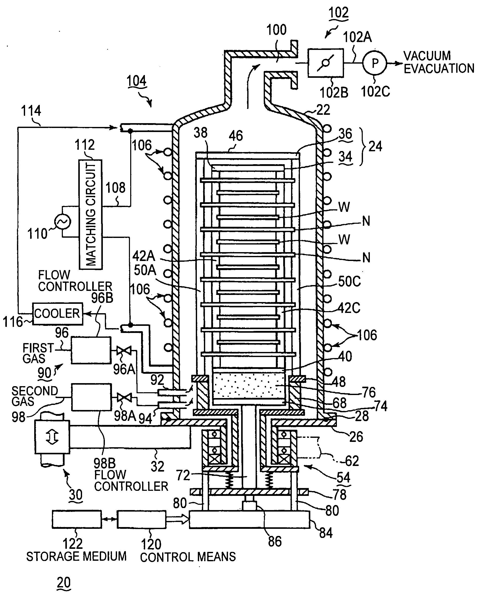
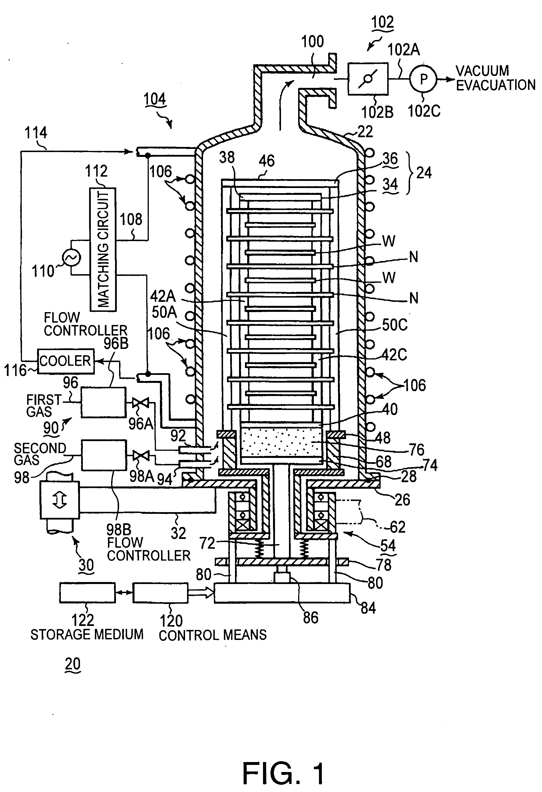
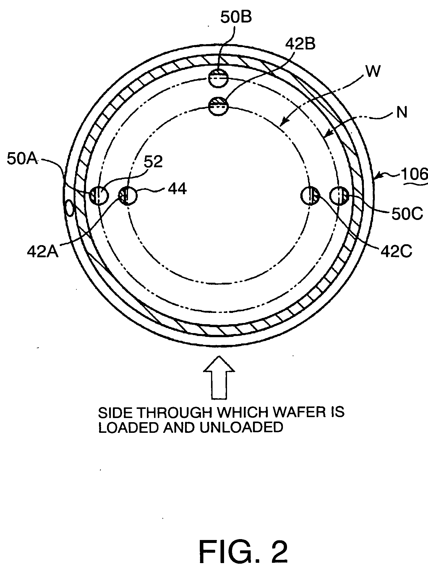
A processing apparatus subjects an object to be processed W to a heat process. The processing apparatus comprises: a processing vessel 22 capable of containing a object to be processed W; a coil part for induction heating 104 that is disposed outside the processing vessel 22; a radiofrequency power source 110 configured to apply a radiofrequency power to the coil part for induction heating 104; a gas supply part 90 configured to introduce a gas into the processing vessel 22; a holding part 24 configured to hold the object to be processed W in the processing vessel 22; and a induction heating element N that is inductively heated by a radiofrequency from the coil part for induction heating 104 so as to heat the object to be processed W. The induction heating element N is provided with a cut groove for controlling a flow of an eddy current generated on the induction heating element.

Description

CROSS REFERENCE TO RELATED APPLICATIONS[0001]This application is based upon and claims the benefit of priority from the prior Japanese Patent Application No. 2008-012000 filed on Jan. 22, 2008, the entire contents of which are incorporated herein by reference.FIELD OF THE INVENTION[0002]The present invention relates to a processing apparatus and a processing method that perform various heat processes such as a film deposition process for depositing a thin film on a surface of an object to be processed such as a semiconductor wafer.BACKGROUND ART[0003]In order to manufacture a semiconductor integrated circuit, various heat processes, such as a film deposition process, an etching process, an oxidation process, a diffusion process, and a modification process, are generally performed to a semiconductor wafer formed of a silicon substrate or the like. For example, a film deposition process among these various heat processes is performed in, e.g., a batch-type film deposition apparatus di...

Claims


Application Information

Patent Timeline
Patent Type & Authority Applications(United States)
IPC IPC(8): H05B6/10H05B6/22
CPCH01L21/67109H01L21/324
Inventor SAWADA, IKUOMATSUURA, HIROYUKITAKAHASHI, TOSHIKI
Owner TOKYO ELECTRON LTD
Why Eureka
Try Eureka