Positive-displacement rotary machine

a rotary machine and positive displacement technology, applied in the field of machine building industry, can solve the problems of weakening the shaft, combining such a machine into a multi-stage machine, and non-uniform flow ra

Inactive Publication Date: 2009-07-23
DIDIN ALEXANDR VLADIMIROVICH +1
View PDF14 Cites 9 Cited by
  • Summary
  • Abstract
  • Description
  • Claims
  • Application Information

AI Technical Summary

Problems solved by technology

Disadvantage of such machines is a complicated configuration of the separator and the piston slot that does not allow contact between them over a large area in order to reduce wear of the friction pair (to reduce an ideal load on the friction pair and extend its service life).
PDRM also has disadvantages: the difficulty of combining such a machine into a multi-stage machine, associated with the fact that the inlet and outlet openings are located on the same side of the piston, and in order to get from one stage to another, a channel is required bypassing the spherical cavity of the body along the rotor axis.
Also considered as disadvantages are: non-uniform flow rate, weak mounting of the piston (which is only partially located inside the groove on the sphere), which also weakens the shaft due to the circular groove, unreliable mounting of the sealing synchronizing element in the slot of the piston (jamming is possible under increased loads).
Unreliable synchr...

Method used


Image

  • Positive-displacement rotary machine
  • Positive-displacement rotary machine
  • Positive-displacement rotary machine

Examples


Embodiment Construction

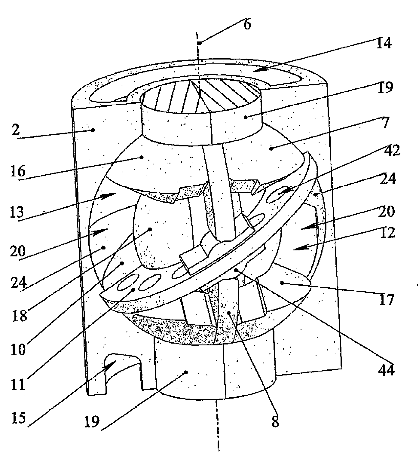
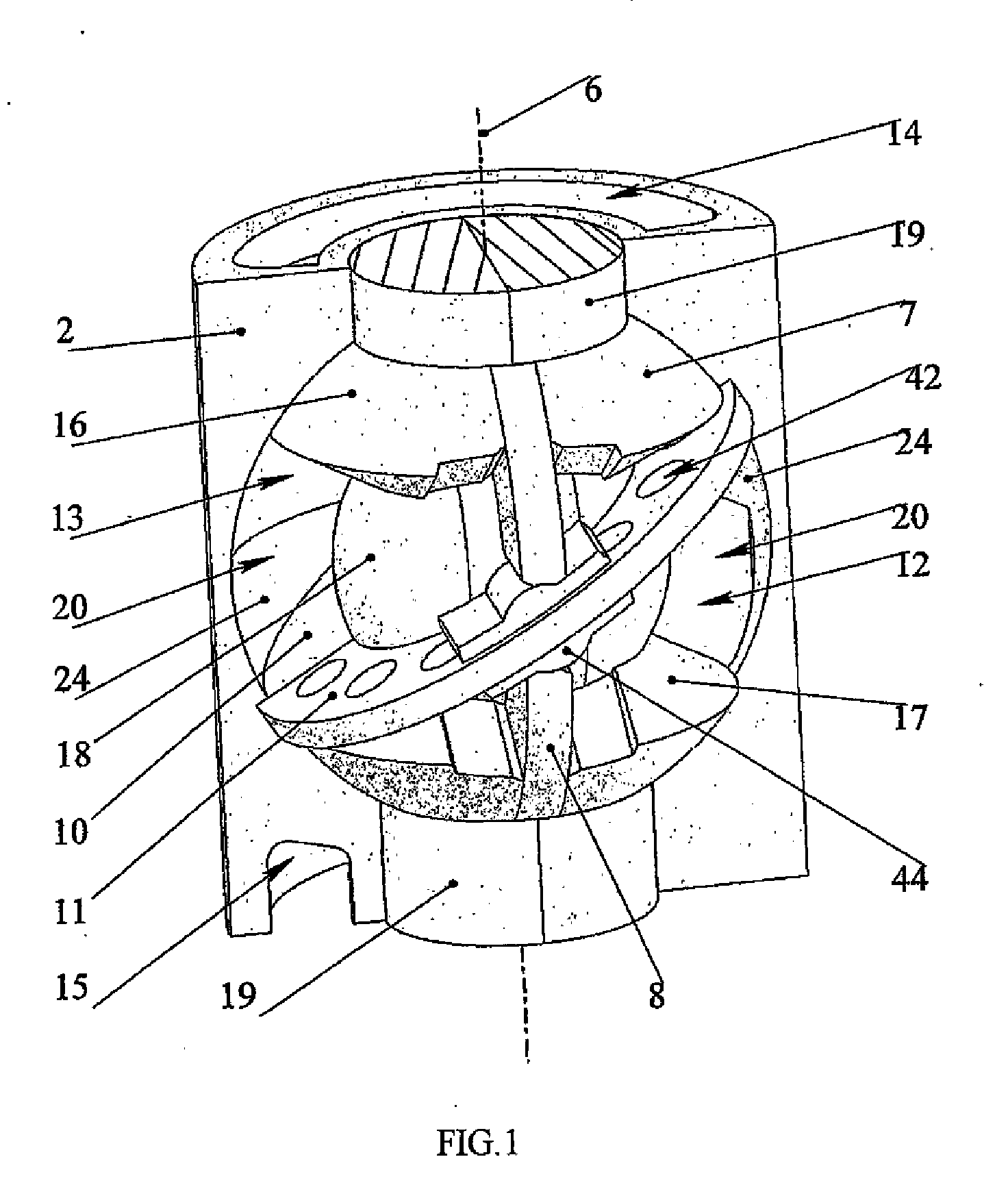
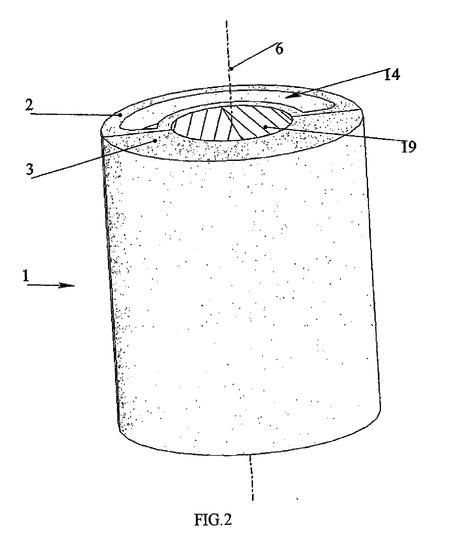
[0139]A positive displacement rotary machine stage (which can be used separately as well) (FIG. 1) is designed as follows. A body 1 (FIG. 2), made of two parts, conditionally (conventionally) called as the ascending (bypass) half 2 (FIG. 3) and the descending (discharge) half 3 (FIG. 4), has a cavity 4 in the form of a segment of a sphere (rather a segment of a torus, which is formed instead of the sphere resulting from tolerances for a rotor axial play) with two holes 5, concentric with it (FIG. 3). A separator 9, made in the form of a washer with an inner spherical hole 41 (FIGS. 1, 3, 4, 5), is mounted in the spherical cavity 4 at an angle to the hole 5 geometrical axis that is the machine geometrical axis 6. To enable assembling, the separator 9 is made of two parts: conditionally ascending (bypass) 10 and descending (discharge) 11, each of which is fixed to the corresponding body parts 2 and 3 (FIGS. 3,4). Through-passes 42 to the other side of the separator 9 are made at one o...


PUM


Abstract

The invention relates to rotary machines provided with nonparallel axes of a rotor and pistons. The inventive positive-displacement rotary machine comprises a body, the working surface of which is embodied in the form of a part of a segment of sphere, a rotor which is provided with a working surface of revolution and which is arranged in the body in such a way that it is rotatable, a ring-shaped concentric working cavity formed by the body and the rotor, a separator which is embodied in the form of a wobble plate, is fixedly arranged in the body and divides the working cavity into two parts. The working surface of the rotor is provided with at least one slot which is embodied along the geometrical axis of rotation thereof and in which a piston in the form of a part of disk is placed in such a way that it is enabled to perform rotational oscillations in the plane thereof. Each piston is provided with a sealable through-slot for the separator passage. At least one through passage, which makes it possible to position input and output ports on the opposite sides of the separator by mutually spacing them along the axis of the rotor, is embodied on one of the areas of the separator, thereby simplifying the combination of stages. Said inventions make it possible to increase the synchronising reliability of the working members of a spherical machine and to use it in a down-hole high-speed multistage high-pressure pump.

Description

FIELD OF THE INVENTION[0001]The invention relates to machine-building industry that is to positive displacement rotary machines which can be used as pumps, compressors, hydraulic drives and others.BACKGROUND OF THE INVENTION[0002]A positive displacement rotary machine (PDRM) (RU 2004133654) having a body with an internal ring cavity is known. A spiral separator with a rotor inside is installed in this cavity. The rotor working surface is a surface of rotation, where there is at least one slot along the rotation axis of the rotor, in each of which a piston partly extending (projecting) from one side of the rotor is rotatably mounted. Besides, the piston has at least one through-slot across its perimeter interacting with the separator for the piston and the rotor rotation synchronization. The machine inlet and outlet openings are spaced along the rotor axis and separated from each other by the separator.[0003]Such machine has the following advantages.[0004]The piston is securely insta...

Claims


Application Information

Patent Timeline
IPC IPC(8): F01C3/00F01C19/00
CPCF04B27/0804
Inventor DIDIN, ALEXANDR VLADIMIROVICHYANOVSKY, ILYA YAKOVLEVICH
Owner DIDIN ALEXANDR VLADIMIROVICH
Why Eureka
Try Eureka