Electric power steering device

a technology of electric power steering and steering wheel, which is applied in the direction of non-deflectable wheel steering, underwater vessels, and registering/indicating the working of vehicles, etc., can solve the problems of significant change in the assist power of the motor, deterioration of steering feeling, and significant change in steering characteristics of the eps, so as to reduce the occurrence of oscillation, and quickly relieve the stuck steering wheel

Inactive Publication Date: 2009-07-23
JTEKT CORP
View PDF4 Cites 20 Cited by
  • Summary
  • Abstract
  • Description
  • Claims
  • Application Information

AI Technical Summary

Benefits of technology

[0016]According to the above-described configuration, however, by selecting a relatively small value (absolute value) as the initial value of the correction amount, it is possible to suppress the occurrence of the inverse assist torque that impedes rotation of the motor due to the deviation in the phase during normal steering operation, and it is also possible to suppress the occurrence of oscillation due to the excessive amount of the rotational angle correction even when the acceleration control is performed. Thus, even when the stuck steering wheel actually occurs, it is possible to quickly relieve the stuck steering wheel by increasing the amount of inverse assist in the acceleration control by increasing the correction amount. As a result, it is made possible to further smooth rotation of the motor and realize better steering feeling with a simple configuration.
[0017]In the above aspect, the motor control signal output part may gradually increase the amount of correction of the rotational angle until the reduction in the follow-up performance is eliminated. With the above configuration, it is possible to optimize the rotational angle correction amount and moderate the variation in the inverse assist torque with increase in the rotational angle correction amount when the stuck steering wheel occurs, with a simple configuration. As a result, it is made possible to help start moving more smoothly after the stuck steering wheel is relieved, whereby it is possible to further improve the steering feeling.
[0018]In the above aspect, the follow-up performance reduction-detecting part may be configured so that, only when the rotational angle of the motor falls within the current restriction range, the follow-up performance reduction-detecting part determines that the reduction in the follow-up performance is detected.
[0019]According to the above-described configuration, it is possible to more accurately detect the situation in which the intensification of the acceleration control by increasing the rotational angle correction amount is effective, that is, detect the occurrence of the stuck steering wheel due to the existence of the deceleration section that is generated due to performing the current restriction, while the physical factors are excluded, such as a contact with a curbstone, reaching to the steering end. As a result, it is made possible to further improve the steering feeling by realizing more smooth rotation of the motor.
[0020]In the above aspect, the follow-up performance reduction-detecting part may be configured so that, when the amount by which a steering torque has been varied since the rotational angle of the motor becomes constant exceeds a predetermined threshold value, the follow-up performance reduction-detecting part determines that the reduction in the follow-up performance is occurring.
[0021]With the above configuration, it is made possible to quickly detect the occurrence of the stuck steering wheel even during running on a low μ road.

Problems solved by technology

However, the steering characteristics of the EPS change significantly due to the discontinuation of the motor control.
However, in the case described above in which an electrification failure occurs in a phase and therefore the motor control is continued with the other two electrification phases, deterioration of steering feeling occurs inevitably due to the occurrence of a torque ripple, in a configuration where a sinusoidal waveform current is applied to each electrification phase, as shown in FIG. 28 (in the illustrated example, the U phase is abnormal, and V and W phases are electrified).
In other words, because a motor current corresponding to a requested torque is not generated, the motor is continuously driven without delivering its true output performance, causing a significant change in the assist power of the motor.

Method used


Image

  • Electric power steering device
  • Electric power steering device
  • Electric power steering device

Examples


first embodiment

[0055]An electric power steering device (EPS) according to the invention is described hereinafter with reference to the drawings.

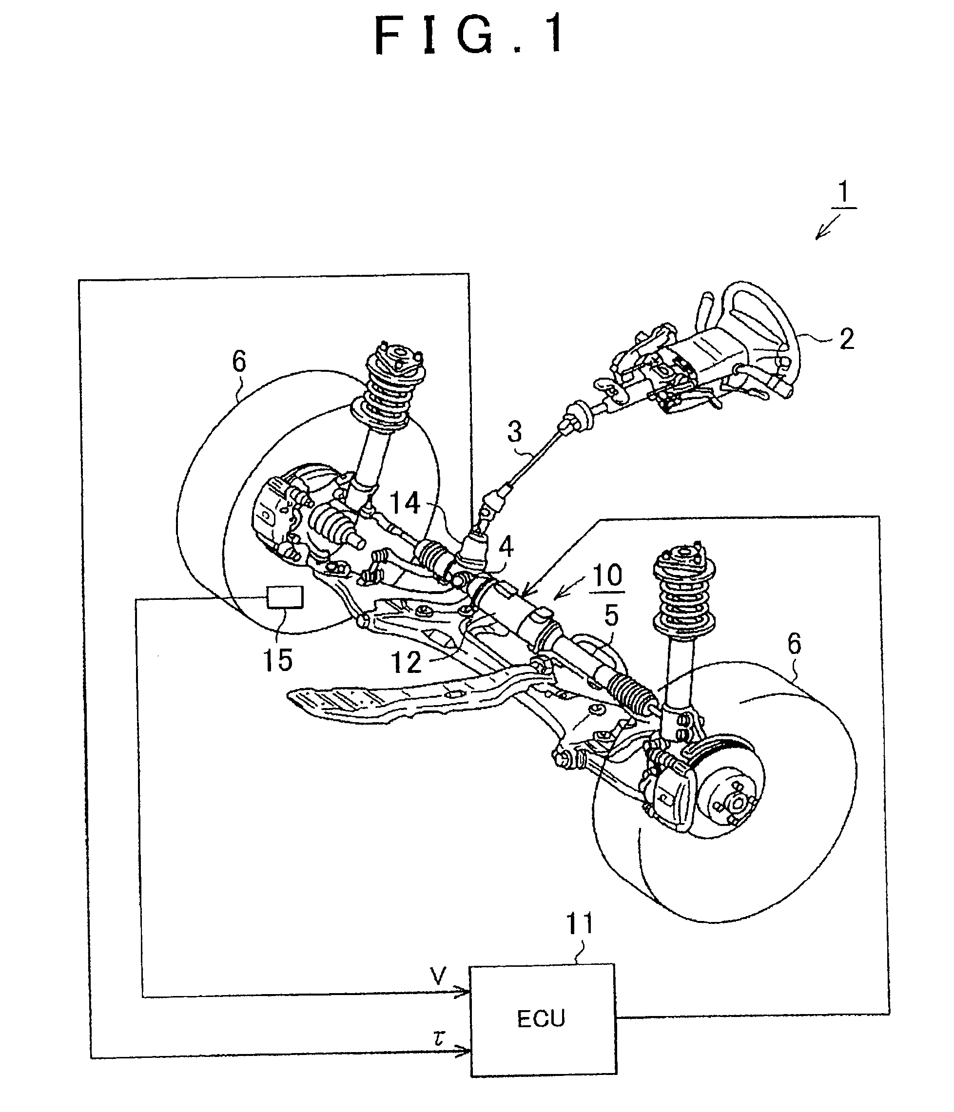
[0056]FIG. 1 is a schematic configuration diagram of an EPS 1 according to the first embodiment. As shown in the diagram, a steering shaft 3 connected to a steering wheel (steering) 2 is connected to a rack 5 via a rack-and-pinion mechanism 4. When a steering operation is performed, the rotation of the steering shaft 3 is converted into a linear motion of the rack 5 by the rack-and-pinion mechanism 4. Then, the linear motion of the rack 5 changes the steering angle of a turning wheel 6.

[0057]The EPS 1 has an EPS actuator 10 which functions as a steering force assisting device for applying an assist power to a steering system to assist its steering operation, and an electrical control unit (ECU) 11, which serves as the control means, for controlling actuation of the EPS actuator 10.

[0058]The EPS actuator 10 of this embodiment is a so-called rack-type EPS ac...

second embodiment

[0162]An electric power steering system is described hereinafter with reference to the drawings.

[0163]A major difference between this embodiment and the above-described first embodiment exists in the mode of the rotational angle correction control during two phase drive. Therefore, for convenience of explanation, the same reference numerals are used for the parts the same as those of the first embodiment, and the explanation of these parts are omitted.

[0164]As shown in FIG. 20, a rotational angle correction controller 50 of this embodiment is provided with an inverse assist correction amount-computing part 51 instead of the first and second correction amount-computing parts 41 and 42 (see FIG. 9) in the rotational angle correction controller 40 of the first embodiment.

[0165]In this embodiment, the inverse assist correction amount-computing part 51 receives the steering torque τ, and the rotational angle θ and the rotational angular velocity ω of the motor 12. The inverse assist cor...

third embodiment

[0189]An electric power steering system (EPS) according to the invention is described hereinafter with reference to the drawings.

[0190]A major difference between this embodiment and the above-described first embodiment exists in the mode of the stuck steering wheel determination to detect reduction in the rotational follow-up performance of the motor. Therefore, for convenience of explanation, the same reference numerals are used for the parts the same as those of the first embodiment, and the explanation of these parts are omitted.

[0191]In the case of the first embodiment (and the second embodiment), basically, it is determined that the stuck steering wheel is occurring provided that it is determined that the rotational angular velocity ω (absolute value thereof) is less than the predetermined threshold value ω1 (see FIG. 19, step 402: YES) despite the fact that the steering torque τ (absolute value thereof) exceeds the predetermined threshold value τ1 (see FIG. 19, step 401: YES)....


PUM


Abstract

The rotational angle correction controller includes a second correction amount-computing part that computes a second correction amount ε2 for correcting the rotational angle θ such that the phase is shifted in the steering operation direction, and the rotational angle correction controller performs the rotational angle correction by adding the computed second correction amount ε2 to the rotational angle θ. Further, the rotational angle correction controller includes a stuck steering wheel determining part that detects the significant reduction in the follow-up performance of the motor with respect to the steering operation that occurs due to the existence of the deceleration section caused by execution of the above-described electric current restriction, that is, the occurrence of the stuck steering wheel. When the occurrence of the stuck steering wheel is detected, the second correction amount-computing part changes the second correction amount ε2 to a value (ε2′) larger than the normal value.

Description

INCORPORATION BY REFERENCE[0001]The disclosure of Japanese Patent Application No. 2008-010834 filed on Jan. 21, 2008 and Japanese Patent Application No. 2008-041484 filed on Feb. 22, 2008 including the specification, drawings and abstract is incorporated herein by reference in its entirety.BACKGROUND OF THE INVENTION[0002]1. Field of the Invention[0003]This invention relates to an electric power steering device.[0004]2. Description of the Related Art[0005]Many of the motor control devices that are used in electric power steering devices (EPS) and the like are provided with an abnormality-detecting means that detects an abnormality when an electrification failure occurs in any of the three phases (any of U, V and W phases) of a motor due to disconnection of a power supply line or a contact failure of a drive circuit. Upon detection of the abnormality, these motor control devices stop the motor control promptly to attain fail safe.[0006]However, the steering characteristics of the EPS...

Claims


Application Information

Patent Timeline
Patent Type & Authority Applications(United States)
IPC IPC(8): G06F17/00B62D5/04B62D6/00B62D119/00B62D137/00H02P6/06H02P6/08H02P6/12H02P6/16H02P6/17H02P6/28
CPCB62D5/046B62D5/0487B62D5/0484
Inventor NOZAWA, TETSUYAEKI, HIROZUMI
Owner JTEKT CORP
Why Eureka
Try Eureka