Method of Controlling a Mechanical Compression Ratio and a Start Timing of an Actual Compression Action

a technology of mechanical compression ratio and start timing, which is applied in the direction of electrical control, process and machine control, etc., can solve the problems of high ratio, delayed closing timing of intake valve, and inability to raise the actual compression ratio that much, so as to improve thermal efficiency and good fuel consumption

Inactive Publication Date: 2009-07-23
TOYOTA JIDOSHA KK
View PDF12 Cites 18 Cited by
  • Summary
  • Abstract
  • Description
  • Claims
  • Application Information

AI Technical Summary

Benefits of technology

[0007]An object of the present invention is to provide a spark ignition type internal combustion engine improved in thermal efficiency at the time of vehicle operation and giving good fuel consumption.

Problems solved by technology

However, in this internal combustion engine, even at the time of engine low load operation, the mechanical compression ratio is made high and the closing timing of the intake valve is delayed, but whether the mechanical compression ratio is higher or lower than at the time of engine medium load operation is unclear and whether the closing timing of the intake valve is later or earlier than at the time of engine medium load operation is unclear.
Further, in this internal combustion engine, whether the actual compression ratio at the time of engine low load operation is higher or lower than at the time of engine medium and high load operation is also unclear.
Further, generally speaking, in an internal combustion engine, the lower the engine load, the worse the thermal efficiency, therefore to improve the thermal efficiency at the time of vehicle operation, that is, to improve the fuel consumption, it becomes necessary to improve the thermal efficiency at the time of engine low load operation.
However, in the above known internal combustion engine, whether the mechanical compression ratio is being made as high as possible so as to obtain the maximum expansion ratio at the time of engine low load operation is unclear.
However, if the actual compression ratio is increased, knocking occurs, so the actual compression ratio cannot be raised that much.
Therefore, in the past, since, even if raising the mechanical compression ratio at the time of engine low load operation, the actual compression ratio could not be raised that much, the mechanical compression ratio was never made that high.
As a result, in the past, there was the problem that a sufficiently high expansion ratio could not be obtained at the time of engine low load operation and accordingly a good fuel consumption could not be obtained commensurate with the increased complexity of the structure.

Method used


Image

  • Method of Controlling a Mechanical Compression Ratio and a Start Timing of an Actual Compression Action
  • Method of Controlling a Mechanical Compression Ratio and a Start Timing of an Actual Compression Action
  • Method of Controlling a Mechanical Compression Ratio and a Start Timing of an Actual Compression Action

Examples


Embodiment Construction

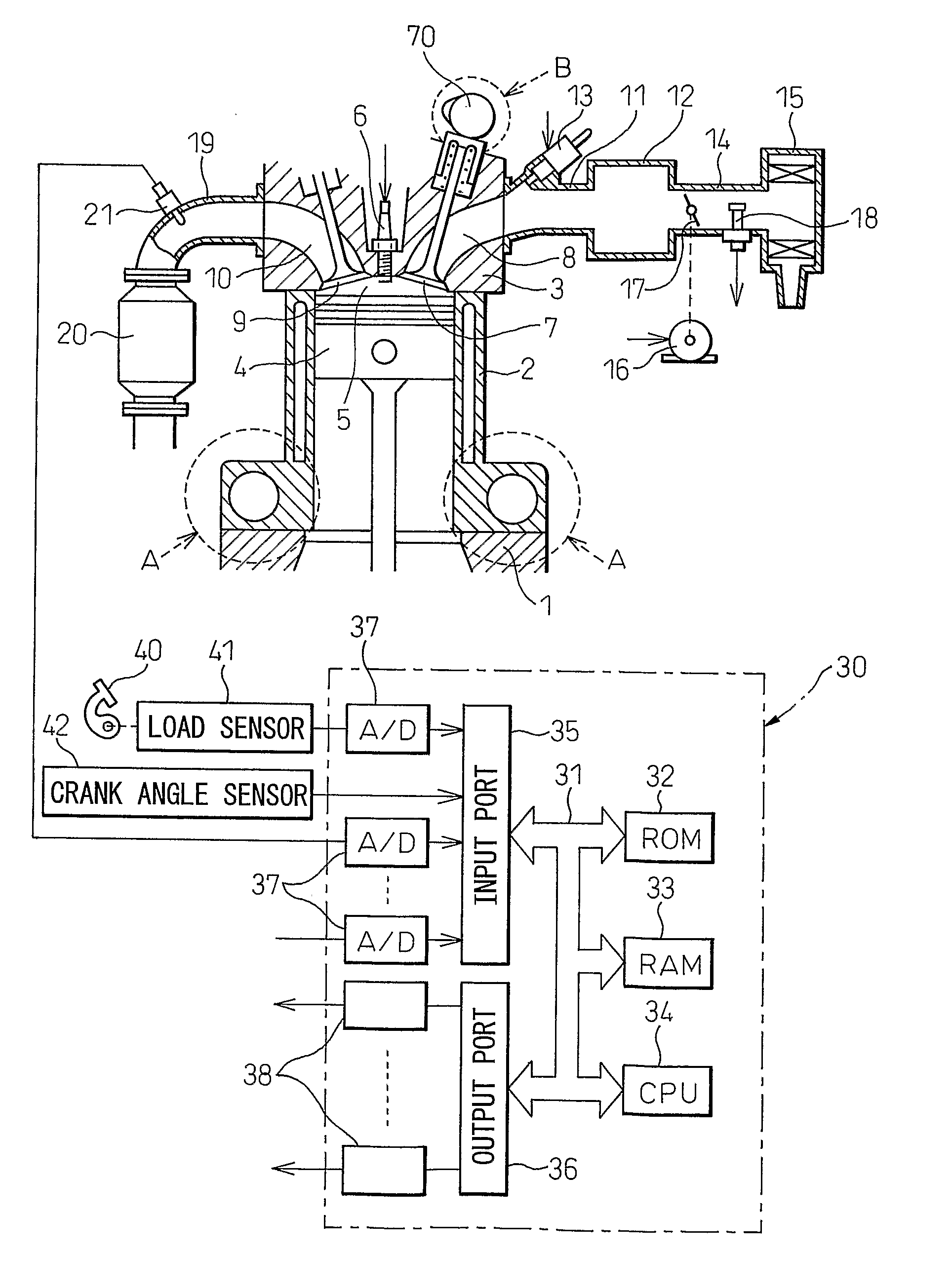
[0021]FIG. 1 shows a side cross-sectional view of a spark ignition type internal combustion engine.

[0022]Referring to FIG. 1, 1 indicates a crank case, 2 a cylinder block, 3 a cylinder head, 4 a piston, 5 a combustion chamber, 6 a spark plug arranged at the top center of the combustion chamber 5, 7 an intake valve, 8 an intake port, 9 an exhaust valve, and 10 an exhaust port. The intake port 8 is connected through an intake branch tube 11 to a surge tank 12, while each intake branch tube 11 is provided with a fuel injector 13 for injecting fuel toward a corresponding intake port 8. Note that each fuel injector 13 may be arranged at each combustion chamber 5 instead of being attached to each intake branch tube 11.

[0023]The surge tank 12 is connected through an intake duct 14 to an air cleaner 15, while the intake duct 14 is provided inside it with a throttle valve 17 driven by an actuator 16 and an intake air amount detector 18 using for example a hot wire. On the other hand, the exh...


PUM


Abstract

An internal combustion engine provided with a variable compression ratio mechanism able to change a mechanical compression ratio and an actual compression action start timing changing mechanism able to change a start timing of an actual compression action. The mechanical compression ratio is made maximum so that the expansion ratio becomes 20 or more at the time of engine low load operation, while the actual compression ratio at the time of engine low load operation is made an actual compression ratio substantially the same as that at the time of engine high load operation.

Description

TECHNICAL FIELD[0001]The present invention relates to a spark ignition type internal combustion engine.BACKGROUND ART[0002]Known in the art is a spark ignition type internal combustion engine provided with a variable compression ratio mechanism able to change a mechanical compression ratio and a variable valve timing mechanism able to control a closing timing of an intake valve, performing a supercharging action by a supercharger at the time of engine medium load operation and engine high load operation, and increasing the mechanical compression ratio and delaying the closing timing of the intake valve as the engine load becomes lower at the time of engine medium and high load operation in the state holding the actual combustion ratio constant (for example, see Japanese Patent Publication (A) No. 2004-218522).[0003]However, in this internal combustion engine, even at the time of engine low load operation, the mechanical compression ratio is made high and the closing timing of the in...

Claims


Application Information

Patent Timeline
Patent Type & Authority Applications(United States)
IPC IPC(8): F02D41/00
CPCF02D13/0238F02D13/0269Y02T10/142F02D2041/001F02D2041/002F02D15/04Y02T10/12F02D13/02F02D15/00
Inventor AKIHISA, DAISUKESAWADA, DAISAKUKAMIYAMA, EIICHI
Owner TOYOTA JIDOSHA KK
Why Eureka
Try Eureka