Heating cooker

a technology for cooking and cookers, which is applied in the field of heating cookers, can solve the problems of large heat loss, difficult cleaning, and unfavorable normal keeping of the temperature in the cooking chamber, and achieve the effect of easy cleaning and high heat transfer ra

Inactive Publication Date: 2009-07-30
TOSHIBA LIFESTYLE PROD & SERVICES CORP
View PDF8 Cites 10 Cited by
  • Summary
  • Abstract
  • Description
  • Claims
  • Application Information

AI Technical Summary

Benefits of technology

[0010]The heating cooker of the present invention can carry out a quick cooking at a high heat transfer rate since hot air is converted to high-speed jet flow, which is caused to impinge on the object to be cooked, whereby heat is applied to the object. Furthermore, the cooking chamber is structured so that hot air is supplied into the cooking chamber through the nozzle holes provided in the ceiling plate and drawn out through the lower parts of the right and left sidewalls. Since the bottom of the cooking chamber is provided with no components such as nozzle holes or suction openings, the interior of the cooking chamber can easily be cleaned.

Problems solved by technology

Since the aforesaid conventional cooking manner has a difficulty in cooking for such a short time, preheating is carried out to keep a temperature in the cooking chamber high when the above-described cooking manner is necessitated.
However, it is unfavorable to normally keep the temperature in the cooking chamber high from the view point of heat efficiency.
However, heat loss is large since the aforesaid oven has a complicated interior structure of the cooking chamber and a hot air circulation path is long.
Furthermore, cleaning is difficult to carry out when a fluid matter such as water content oozing from the object or small pieces of the object enters the hot air circulation path.
However, detaching the components is troublesome and a hot air source is disposed at the rear of the cooking chamber so that hot air is supplied through both of upper and lower surfaces, whereupon the temperature becomes higher at a location near to the heat source such that cooking becomes uneven.
Furthermore, since hot air suction openings through which hot air in the cooking chamber is drawn out are provided in a rear surface, hot air not contributing to cooking is drawn out through the openings, reducing the hot air drawing efficiency.

Method used


Image

  • Heating cooker
  • Heating cooker
  • Heating cooker

Examples


first embodiment

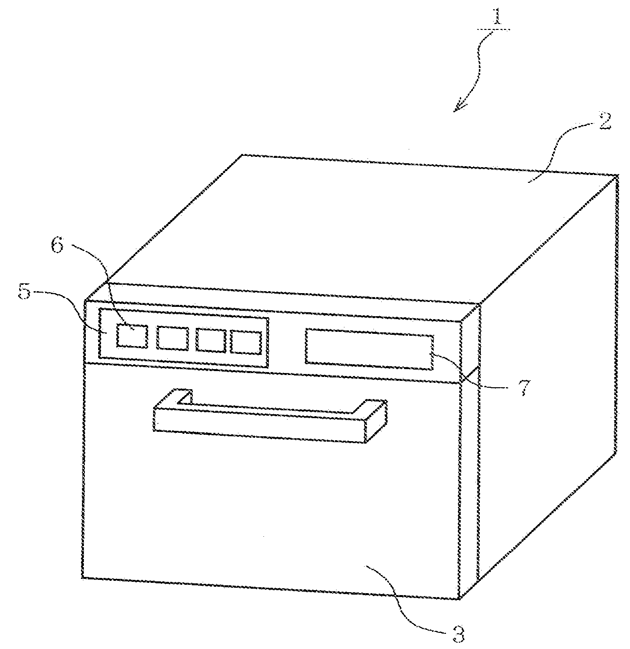
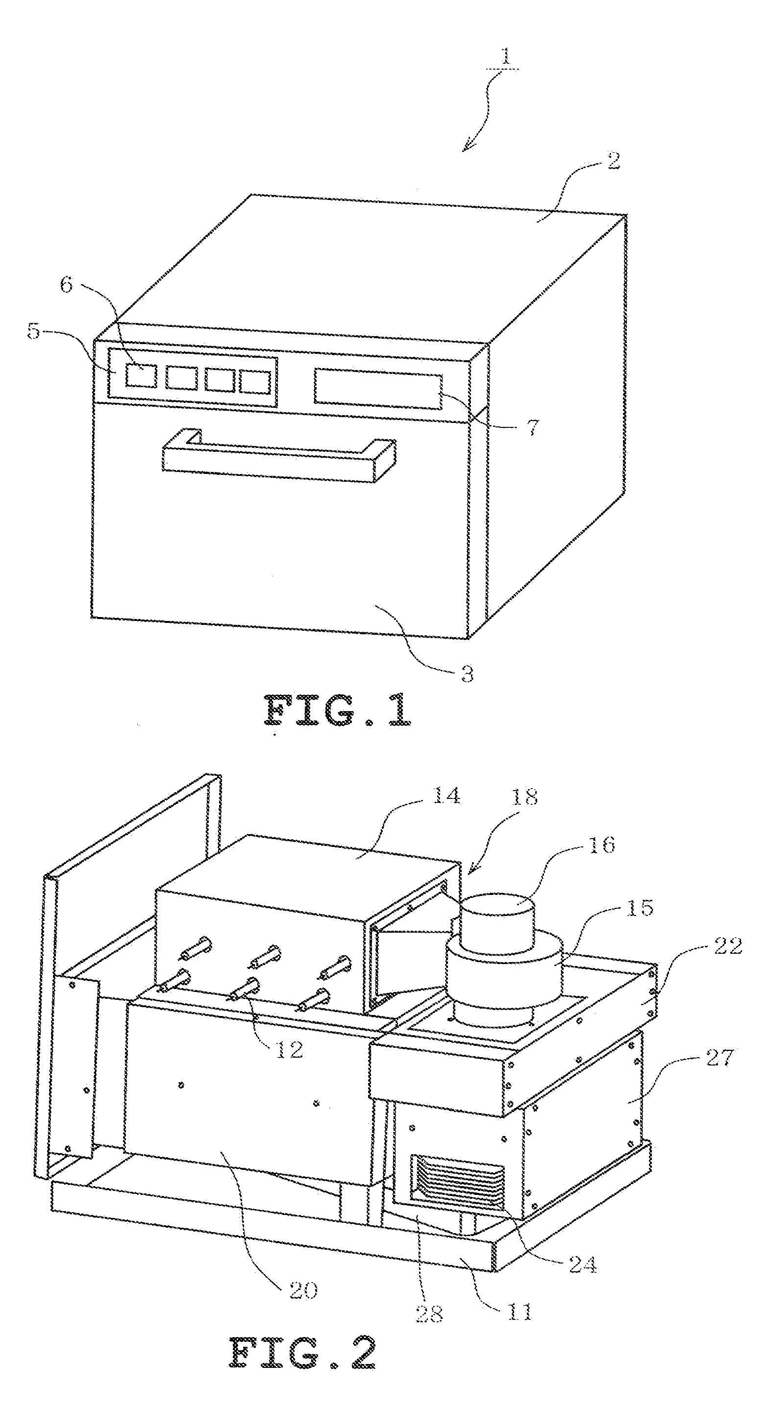
[0047]The invention will be described in more detail with reference to the accompanying drawings. FIGS. 1 to 20 illustrate a first embodiment of the heating cooker in accordance with the present invention. FIG. 1 is a perspective view showing an appearance of the heating cooker 1. The heating cooker 1 includes a cabinet 2 serving as an outer shell. A door 3 is mounted on a front so as to be caused to pivot forward thereby to be opened. An upper part of the door 3 serves as an operation panel 5. An operation switch 6 setting cooking conditions, a display 7 displaying set contents, cooking course and the like.

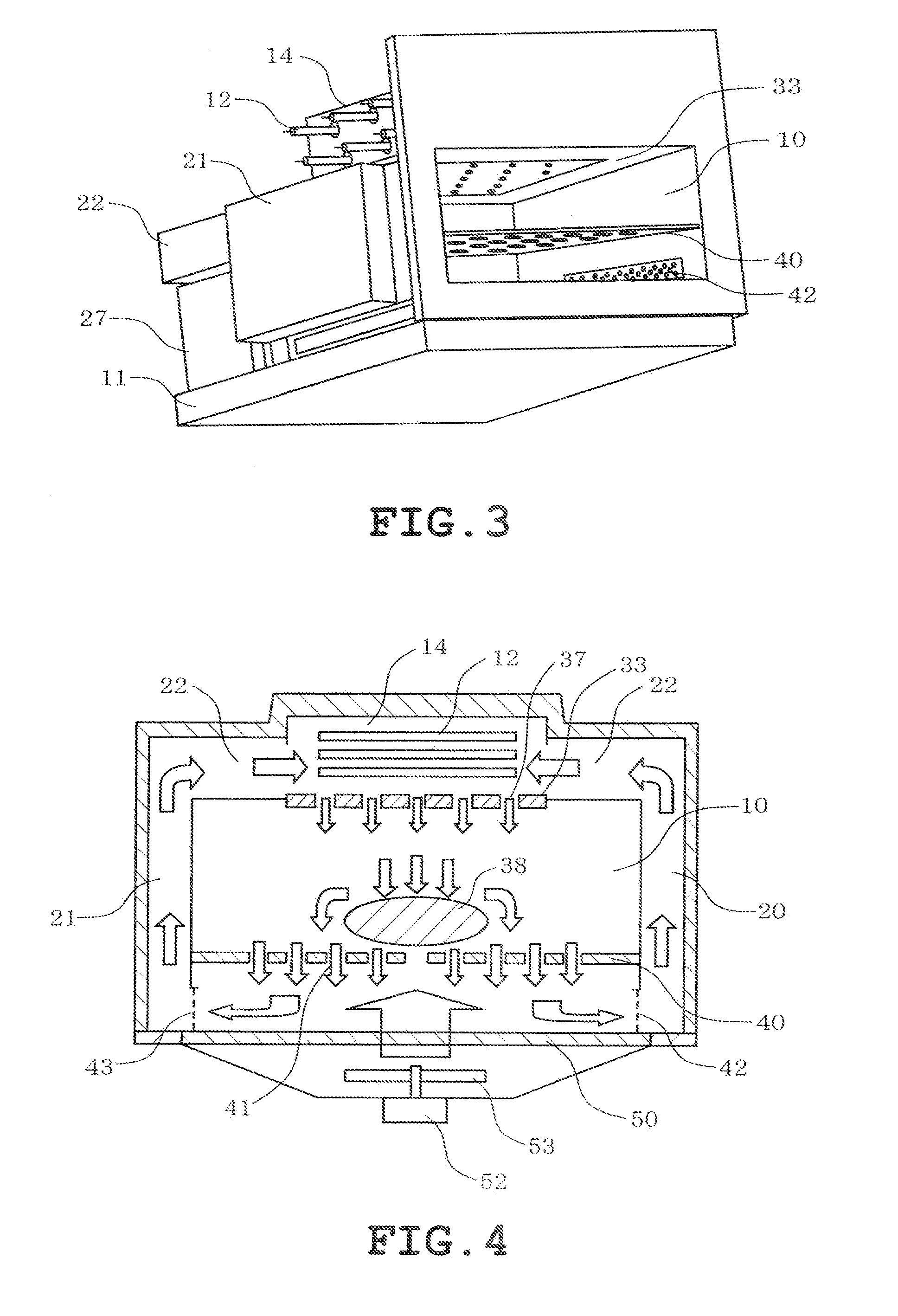
[0048]FIG. 2 is a perspective view of the cooking chamber as viewed from obliquely below at the rear with a cabinet and door being eliminated. FIG. 3 is a perspective view of the same state as viewed from obliquely below at the front. A box-shaped cooking chamber 10 is mounted on a lower frame 11 so as to be located in the central interior of the cabinet 2. The cooking chamber 10...

second embodiment

[0109]FIGS. 21 to 33 illustrate a second embodiment of the heating cooker in accordance with the present invention. The second embodiment differs from the first embodiment in that another shelf plate is provided which can further improve the heating efficiency, instead of the shelf 40. Differences of the second embodiment from the first embodiment will primarily be described.

[0110]FIGS. 21 and 22 schematically show hot air flows in the in the heating cooker 1. FIG. 21 shows a hot air flow as viewed from the front, and FIG. 22 shows a hot air flow as viewed from the right sidewall. In FIGS. 21 and 22, the shelf plate 80 on which the object 38 to be cooked is placed is provided in the cooking chamber 10. A left opening 81 is defined on the left of the shelf plate 80 and a right opening 82 is defined on the right of the shelf plate 80. Furthermore, a rear opening 83 is defined in the rear of the shelf plate 80 and a front opening 84 is defined in front of the shelf plate 80.

[0111]The h...

third embodiment

[0137]FIGS. 34 and 35 illustrate a third embodiment of the invention. Differences of the third embodiment from the second embodiment will be described in the following. In the third embodiment, a flat shelf plate 101 is used instead of the above-described shallow dish-shaped shelf plate 80. FIG. 34 shows the surface of the shelf plate 101 and FIG. 35 shows the underside of the shelf plate 101. The aforesaid convex portions 84 are provided on the surface of the shelf plate 101. The recess 87 is formed in the upper end of each convex portion 84. Generally L-shaped convex portions 102 are formed on four corners of the underside of the shelf plate 101. The convex portions 102 correspond to corners of the underside of the shelf plate 80. The convex portions 102 are fitted in the inner frame 92 of the mounting frame 79 so that the shelf plate 101 is positioned. Consequently, the third embodiment can achieve the same effect as the second embodiment.


PUM


Abstract

A heating cooker having a box-like cooking chamber for receiving an object to be cooked, and a hot air generator having an electric heater heat source and a blower. Hot air produced by the hot air generator is caused to impinge on the object as a high-speed jet flow from nozzle holes formed in a ceiling plate of the cooking chamber. The hot air after the impingement is sucked by the blower from hot-air suction openings formed in left and right sidewall lower sections of the cooking chamber and is returned for recirculation to the hot-air generator.

Description

TECHNICAL FIELD[0001]The present invention relates to a heating cooker to which is applied an impinging jet heat transfer technique in which heat is transferred by impinging high-speed hot air blast on an object to be cooked.BACKGROUND ART[0002]Cooking from thawing to doing an object to be cooked has conventionally been carried out by heating the inside of an object to be cooked by microwave heating with simultaneous vertical application of radiant heat from a heater or circulating in a cooking chamber hot air generated by a heater disposed at the rear of the cooking chamber, using a fan so that an entire atmosphere temperature in the cooking chamber is increased.[0003]Convenience stores etc. provide a service of cooking frozen food purchased by a customer by executing cooking from thawing to doing the food for a short time of 60 to 90 seconds. Since the aforesaid conventional cooking manner has a difficulty in cooking for such a short time, preheating is carried out to keep a tempe...

Claims


Application Information

Patent Timeline
Patent Type & Authority Applications(United States)
IPC IPC(8): H05B6/64
CPCF24C15/16A21B1/245A21B3/04F24C7/062F24C15/162F24C15/2007
Inventor NODA, TOMIMITSUFURUTA, KAZUHIROYONEKURA, MASAJIIKEDA, YOSHIO
Owner TOSHIBA LIFESTYLE PROD & SERVICES CORP
Why Eureka
Try Eureka