
Zinc Anode Battery Using Alkali Ion Conducting Separator

Inactive Publication Date: 2009-07-30
CERAMTEC
View PDF101 Cites 69 Cited by
  • Summary
  • Abstract
  • Description
  • Claims
  • Application Information

AI Technical Summary

Benefits of technology

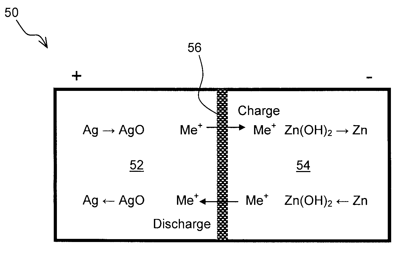
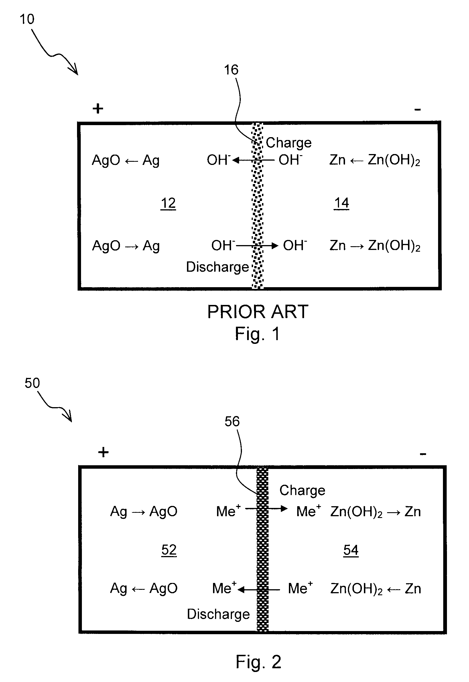
[0013]In one embodiment of the invention, the separator is a substantially non-porous ceramic separator material. Without being bound by theory, it is presently believed that dendrite formation and / or penetration of dendrites from the anode to the cathode may be substantially reduced or eliminated by using a substantially non-porous, alkali ion conducting separator.
[0028]The use of an alkali-ion conductive, substantially non-porous separator disposed between the electrodes inhibits or prevents dendrite formation and / or the penetration of dendrites from the zinc electrode to the opposite electrode in the battery. The non-porous separator also advantageously prevents transport of unwanted species from one electrode to the other and substantially eliminates capacity loss and self discharge. Also any additives added to improve the performance of the electrodes will be confined to the respective compartments by the non-porous ceramic separator.

Problems solved by technology

However, one of the major problems relative to zinc-containing anodes has been the relatively short life of such cells due to the formation of harmfully excessive zinc dendrites during the recharging cycle, which tend to cause shorting.
The electrolyte used in the zinc anode battery is alkaline.
Presently, a major problem in a rechargeable alkaline-zinc cell is the extended formation of deleterious zinc dendrite overgrowth during the recharging cycle which short out and thereby destroy the cell.
These zinc metal dendrites, forming as an overgrowth on the normal initial zinc deposit on the negative electrode (anode) during charge, tend to rapidly span the narrow gap between the positive and negative electrodes and short circuit the cell by forming a current-conducting bridge, not only at the edges of the electrode, but also where their pointed ends penetrate through the porous membranes and separators located between the positive and negative electrodes, thus causing short circuiting of the cells after only a very few discharge and recharge cycles.
Another problem encountered with porous separators is the migration of soluble and insoluble species from anode to cathode and vice-versa which result in loss of capacity either on the shelf or over the course of cell cycling.

Method used


Image

  • Zinc Anode Battery Using Alkali Ion Conducting Separator
  • Zinc Anode Battery Using Alkali Ion Conducting Separator
  • Zinc Anode Battery Using Alkali Ion Conducting Separator

Examples


example 1

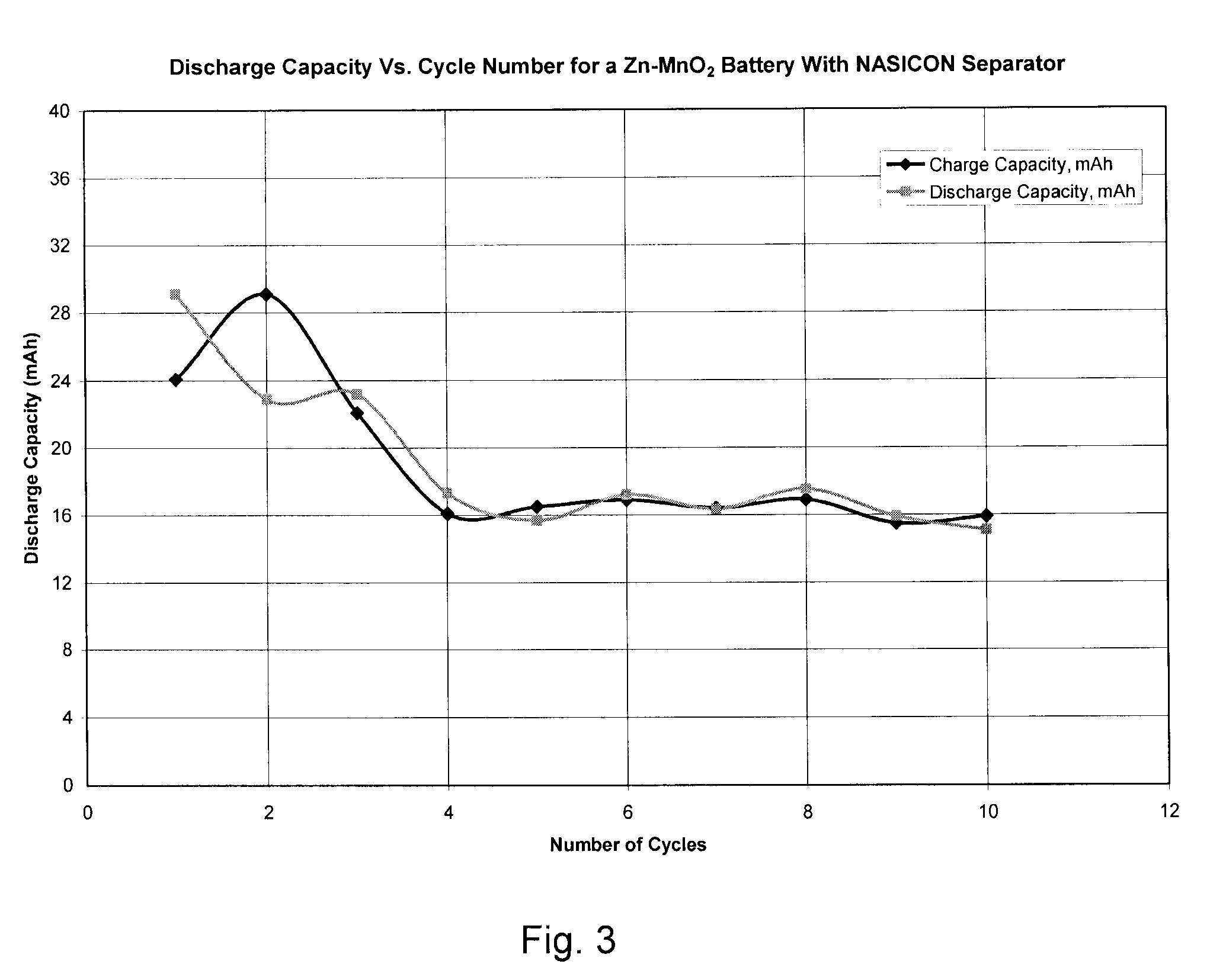
Construction and Testing of Zn—NaSICON—MnO2 Battery

[0074]A Zn—MnO2 battery was constructed with NaSICON as the separator instead of a microporous separator. Battery grade manganese dioxide was purchased from Aldrich. Battery grade low gassing Zn metal powder was obtained from a commercial battery source. 50 wt. % aqueous sodium hydroxide was added such that stoichiometric amount of sodium hydroxide was present in the anode. Note that sodium hydroxide is not just an electrolyte but a participant in the anodic discharge reaction as follows:

Zn+2NaOHZn(OH)2+2Na++2e−

[0075]The opposite electrode or cathode contained about 20 wt. % graphite to improve the electrical conductivity. 25 wt. % NaOH was added to the MnO2 cathode such that excess water was present in the catholyte. Note that water is a participant in the cathodic reaction as follows:

MnO2+H2O+Na++e−MnOOH+NaOH

[0076]A stainless steel current collector was used with the zinc anode. Nickel current collector was used for the second ele...


PUM

PropertyMeasurementUnit
Electrical conductoraaaaaaaaaa
Electric potential / voltageaaaaaaaaaa
Electric propertiesaaaaaaaaaa

Abstract

A zinc anode storage battery comprising a first electrode containing zinc or a zinc alloy, a second electrode containing an oxidizing material capable of electrochemical reduction by zinc, an alkaline electrolyte, and a substantially non-porous, alkali-ion conducting separator provided between the first electrode and the second electrode. The alkali conducting separator may be a solid alkali metal ion super ion conducting material, wherein the alkali metal is Na, K, or Li.

Description

BACKGROUND OF THE INVENTION[0001]This invention relates to a zinc anode battery that includes a non-porous, alkali ion conducting separator. The invention further relates to rechargeable zinc anode batteries that inhibit zinc dendrite formation.[0002]Due to its relatively low price and good electrochemical properties, zinc has long been a desirable ingredient for the negative electrode or anode in rechargeable batteries and electrochemical cells, particularly in cells employing alkaline electrolytes. However, one of the major problems relative to zinc-containing anodes has been the relatively short life of such cells due to the formation of harmfully excessive zinc dendrites during the recharging cycle, which tend to cause shorting.[0003]FIG. 1 shows a schematic representation of zinc anode battery 10 having a positive electrode 12, a negative electrode 14, and a separator 16. The separator provides electrical isolation between the electrodes while still allowing efficient ionic dif...

Claims


Application Information

Patent Timeline
IPC IPC(8): H01M10/36H01M10/44
CPCC04B35/447C04B2235/3203H01M10/39C04B2235/3232H01M10/36C04B2235/3217Y02E60/10Y02P70/50
Inventor JOSHI, ASHOK V.GORDON, JOHN HOWARDBHAVARAJU, SAI
Owner CERAMTEC
Learn More