Aggregate substrate, production method of aggregate substrate, and varistor
a technology of aggregate substrate and production method, which is applied in the direction of resistor details, inorganic insulators, ceramics, etc., can solve the problems of heat generation of electronic devices during operation, deterioration of the properties of the device itself, and warpage of the aggregate substrate, so as to achieve efficient dissipation of heat generated
- Summary
- Abstract
- Description
- Claims
- Application Information
AI Technical Summary
Benefits of technology
Problems solved by technology
Method used
Image

Examples
first embodiment
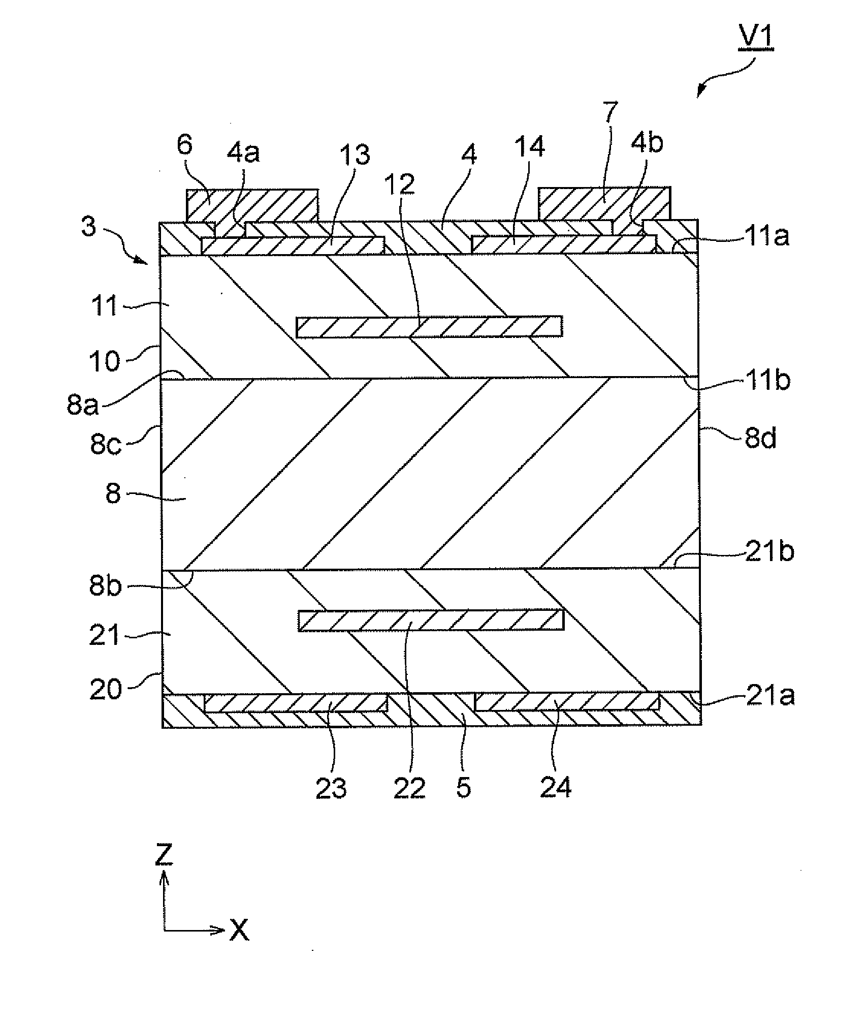
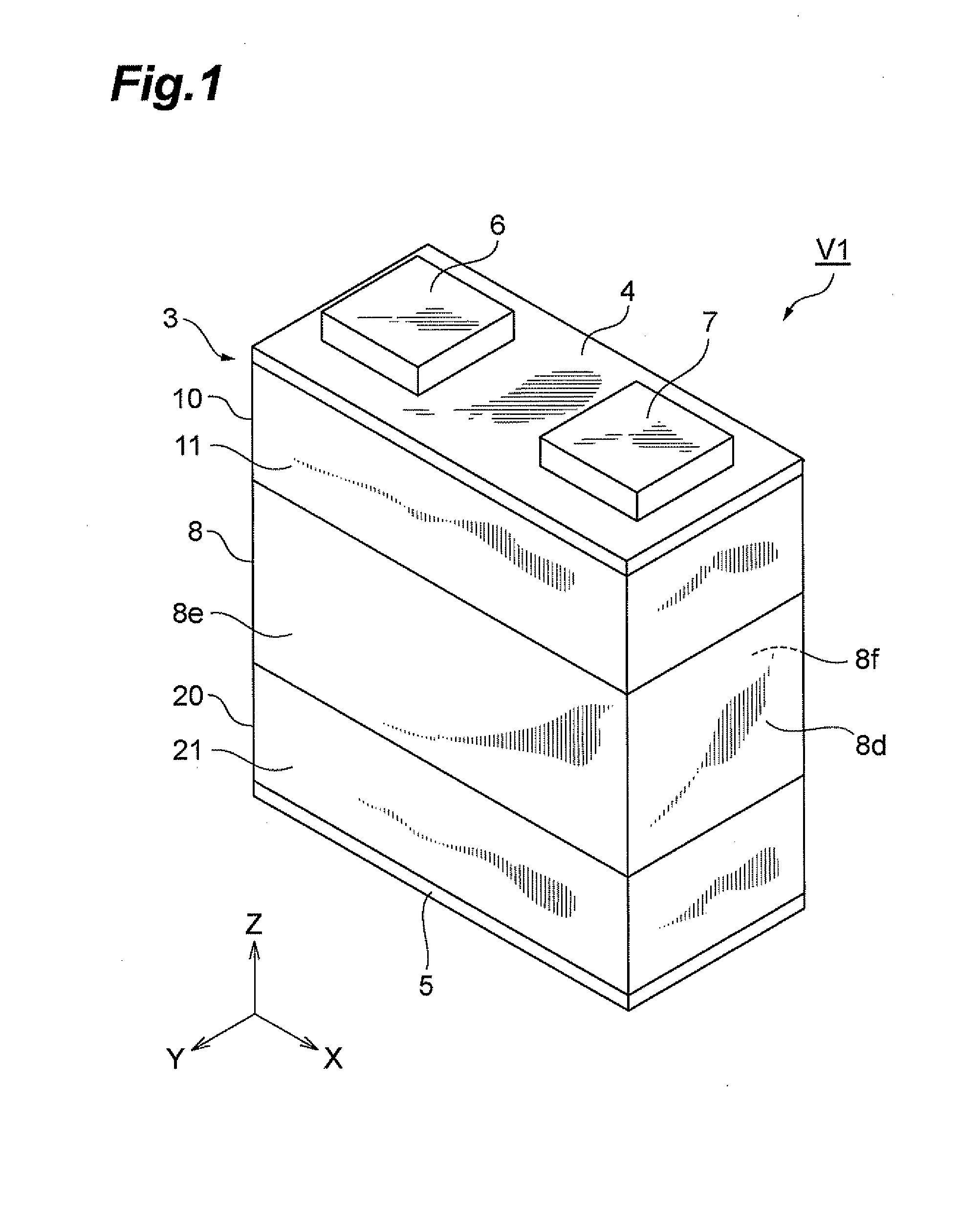
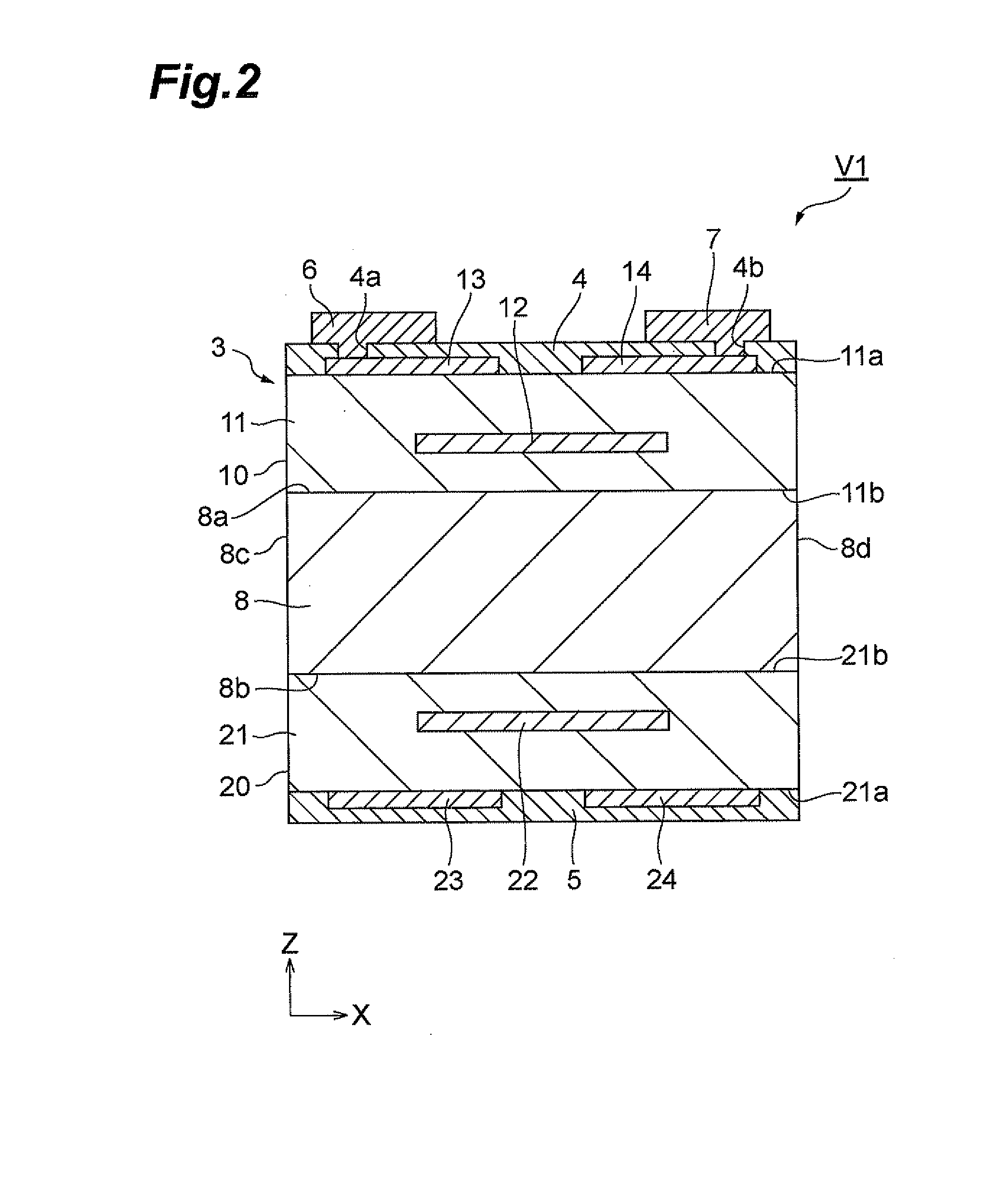
[0046]FIG. 1 is a schematic perspective view of the varistor according to the first embodiment. FIG. 2 is a schematic sectional view of the varistor according to the first embodiment. As shown in FIGS. 1 and 2, the varistor V1 of the first embodiment has an element body 3 of a nearly rectangular parallelepiped shape, insulating layers 4, 5 formed on the top and bottom surfaces of the element body 3, and a pair of external electrodes 6, 7. The element body 3 has a heat dissipation part 8 of a nearly rectangular parallelepiped shape, and first and second varistor parts 10, 20 laid on the top and bottom surfaces of the heat dissipation part 8. The vertical direction of the element body 3 is defined as a Z-direction in an XYZ orthogonal coordinate system.
[0047]The first varistor part 10 includes a varistor element body 11, an internal electrode 12, and a pair of surface electrodes 13, 14. The varistor element body 11 is of a nearly rectangular parallelepiped shape and has faces 11a and ...
second embodiment
[0090]The varistor according to the second embodiment of the present invention will be described. FIG. 12 is a schematic sectional view showing the varistor according to the second embodiment of the present invention. The varistor V2 shown in FIG. 12 has no surface electrode and is different in a configuration of internal electrodes from the varistor V1 of the first embodiment. The varistor V2 has an element body 3A instead of the element body 3 and this element body 3A has first and second varistor parts 60, 70 instead of the first and second varistor parts 10, 20.
[0091]The first varistor part 60 includes a varistor element body 61 of a nearly rectangular parallelepiped shape, a pair of internal electrodes 62, 63 facing each other in the varistor element body 61, and penetrating conductors 64, 65. The varistor element body 61 has a face 61a and a face 61b facing each other in the Z-direction. An insulating layer 4 is arranged on the face 61a and the face 61b is in contact with the ...
third embodiment
[0111]The varistor according to the third embodiment of the present invention will be described below. FIG. 15 is a schematic sectional view showing the varistor according to the third embodiment of the present invention. The varistor V3 shown in FIG. 15 has an element body 3B, insulating layers 4, 5, a 300 pair of external electrodes 6, 7, and a pair of external electrodes 76, 77. The element body 3B has a first varistor part 60, a second varistor part 70, and a heat dissipation part 80.
[0112]The first varistor part 60 includes penetrating conductors 85, 86, in addition to the aforementioned internal electrodes 62, 63 and penetrating conductors 64, 65. The penetrating conductor 85 extends in the Z-direction, one end of which is physically and electrically connected to the internal electrode 62 and the other end of which is exposed from the face 61b. The penetrating conductor 86 extends in the Z-direction, one end of which is physically and electrically connected to the internal ele...
PUM
| Property | Measurement | Unit |
|---|---|---|
| temperature | aaaaa | aaaaa |
| temperature | aaaaa | aaaaa |
| nonlinear voltage-current characteristics | aaaaa | aaaaa |
Abstract
Description
Claims
Application Information
 - R&D
- Intellectual Property
- Life Sciences
- Materials
- Tech Scout
- Unparalleled Data Quality
- Higher Quality Content
- 60% Fewer Hallucinations
Browse by: Latest US Patents, China's latest patents, Technical Efficacy Thesaurus, Application Domain, Technology Topic, Popular Technical Reports.
© 2025 PatSnap. All rights reserved.Legal|Privacy policy|Modern Slavery Act Transparency Statement|Sitemap|About US| Contact US: help@patsnap.com