
Sound field measuring method and sound field measuring device

a measurement method and sound field technology, applied in the direction of vibration measurement in solids, digital computer details, instruments, etc., can solve the problems of deterioration of s/n ratio in the frequency band, and achieve the effect of high s/n ratio, easy generation, and high s/n ratio

Active Publication Date: 2009-08-06
PANASONIC INTELLECTUAL PROPERTY CORP OF AMERICA
View PDF3 Cites 9 Cited by
  • Summary
  • Abstract
  • Description
  • Claims
  • Application Information

AI Technical Summary

Benefits of technology

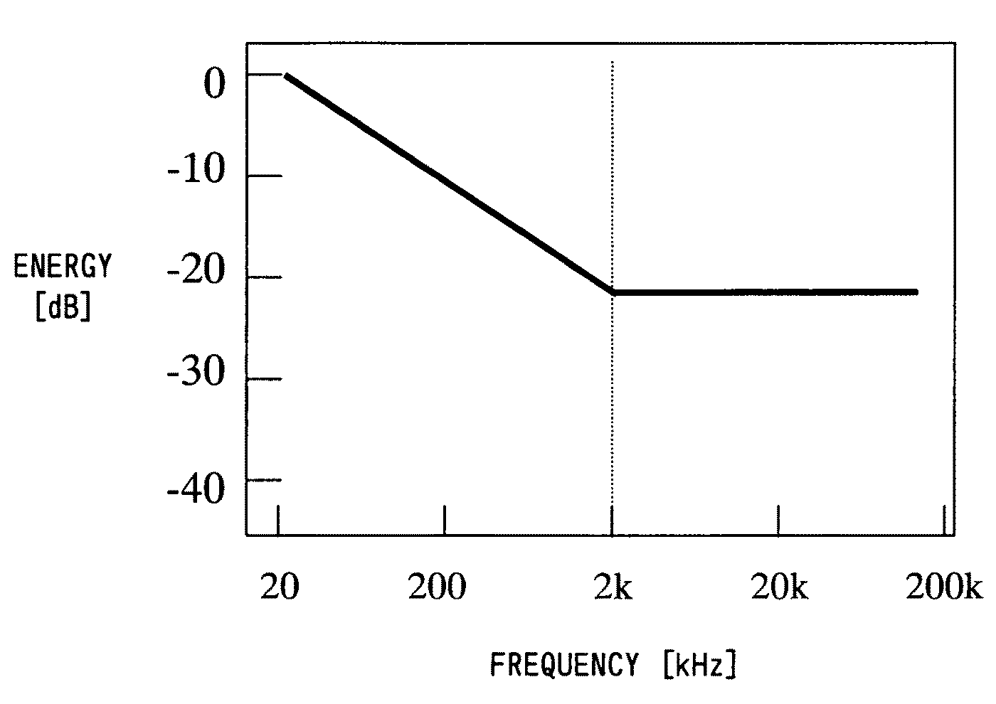
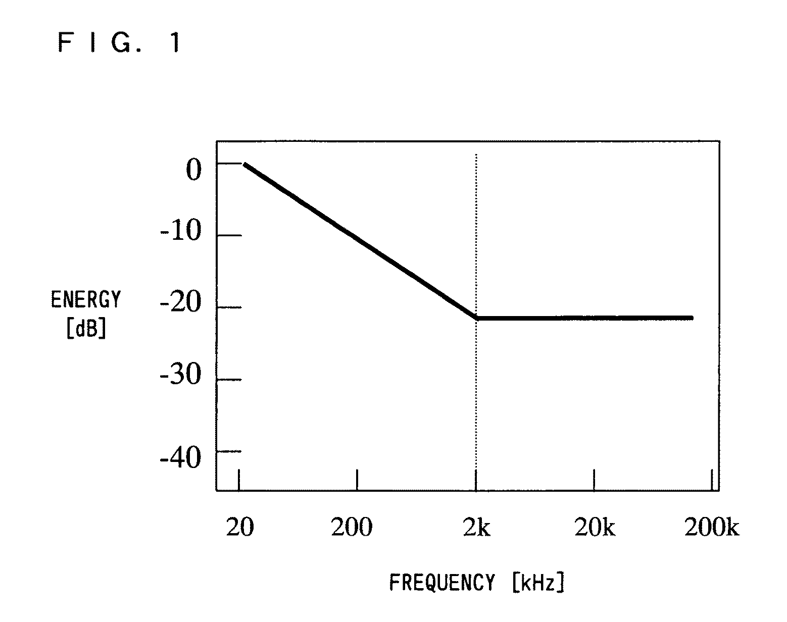
[0032]According to the above first aspect, the frequency spectrum of the measurement signal has at least one change point such that the shape of the frequency spectrum corresponds to the frequency spectrum of the background noise of the sound field space, and as a result, a high S / N ratio is obtained between the measurement signal and the frequency spectrum of the background noise. This allows a sound field measurement to be performed in which a high S / N ratio is obtained over a wide frequency band, e.g., from 20 Hz to 100 kHz.
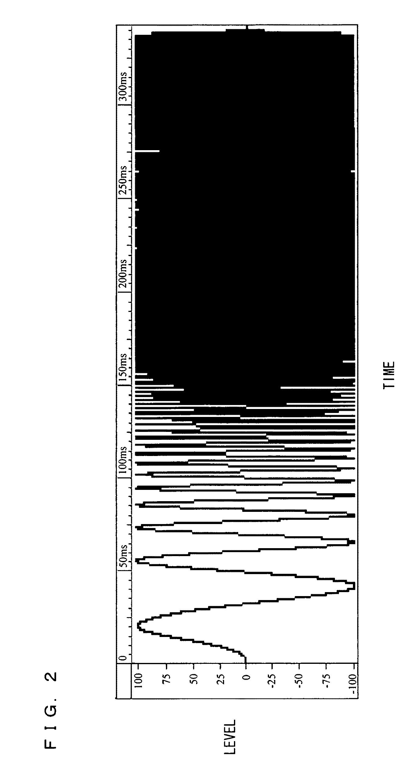
[0033]According to the above second embodiment, the sinusoidal signal is used whose frequency is swept by different sweep manners at respective frequencies higher and lower than the change point, and this allows an energy level of the sinusoidal signal to be easily adjusted between frequency bands respectively higher and lower than the frequency of the change point. As a result, the measurement signal, which has a frequency spectrum corresponding to the shape of the frequency spectrum of the background noise of the sound field to be measured, can be easily generated, and this allows the measurement to be performed in which a high S / N ratio is obtained.
[0034]According to the above third aspect, the measurement signal is a signal having a frequency spectrum corresponding to the frequency spectrum of a general background noise whose energy level is high in a low frequency band and substantially fixed in a high frequency band. This allows the measurement to be performed in which a high S / N ratio is obtained particularly in the high frequency band where the energy level is substantially fixed.
[0035]According to the above fourth aspect, in the high frequency band no lower than the change point, a characteristic of the frequency spectrum of the measurement signal is such that the energy level of the measurement signal increases in accordance with an increase in frequency. This alleviates a problem caused by viscous resistance of air in that energy attenuation increases in accordance with an increase infrequency. This allows the sound field measurement to be performed in which an S / N ratio stably high over a wider frequency band is obtained.
[0036]According to the above fifth aspect, used as the measurement signal is a signal which allows a desired S / N ratio to be obtained for the shape of the frequency spectrum of the background noise, and this allows the measurement to be performed in which the desired S / N ratio is obtained.
[0037]According to the above sixth aspect, the frequency spectrum of the measurement signal is such that in each of the frequency bands separated by the change points, the measurement signal has an energy level corresponding to the energy level of the background noise. This allows the measurement to be performed in which a desired S / N ratio is obtained for each of the frequency bands.

Problems solved by technology

Accordingly, the above-described conventional sound field measuring method has a problem in that an S / N ratio deteriorates in the frequency band A, because the lower the frequency in the frequency band A, the higher is the energy level of the background noise therein.

Method used


Image

  • Sound field measuring method and sound field measuring device
  • Sound field measuring method and sound field measuring device
  • Sound field measuring method and sound field measuring device

Examples


first embodiment

[0067]First, a measurement signal according to the present invention will be described with reference to FIG. 1. FIG. 1 shows an exemplary frequency spectrum of the measurement signal according to the present invention.

[0068]Generally, a frequency spectrum of a background noise (hereinafter, referred to as a background noise spectrum) is such that an energy level of the background noise is high at a low frequency. The background noise contains sound energy existing in a sound field space, for which an impulse response is measured, and distortion of a mechanical or electrical system included in a measuring system of the entire sound field measuring device. The background noise spectrum as shown in FIG. 10 shows the energy level increasing in a frequency band A in accordance with a decrease in frequency. However, in a frequency band B, the background noise spectrum shows the energy level substantially fixed regardless of the frequency.

[0069]Thus, the background noise spectrum does not...

second embodiment

[0096]Next, a sound field measuring device according to a second embodiment of the present invention will be described. Although the sound field measuring device according to the present embodiment is realized by a same configuration as that of the sound field measuring device according to the first embodiment shown in FIG. 7, the second embodiment is different from the first embodiment in that the measurement program for measuring the impulse response is differently operated on the general-purpose PC 1. To be specific, the present embodiment is different from the first embodiment in that in the present embodiment, the background noise of the measuring system is measured, and the measurement signal to be reproduced in the sound field space 9 is generated based on a result of the measurement. Hereinafter, a description is given with a focus on this difference.

[0097]FIG. 9 is an operation flowchart of the measurement program for measuring the impulse response, which is operated on the...


PUM


Abstract

A sound field measuring device according to the present invention uses a measurement signal which has at least one change point and whose frequency spectrum has a shape corresponding to a shape of a frequency spectrum of a background noise. This enables a sound field measurement, which is for measuring an impulse response or transfer function of a sound field space which is a linear time-invariant system to be measured, to be performed with a high S / N ratio over a wide frequency band.

Description

TECHNICAL FIELD[0001]The present invention relates to a sound field measuring method and sound field measuring device for measuring an impulse response or transfer function of a sound field space such as a listening room or vehicle interior space, and particularly to a sound field measuring method and sound field measuring device using a measurement signal which allows a high S / N ratio to be obtained over a wide frequency band.BACKGROUND ART[0002]Conventionally, there has been a known measurement method for sound field measurement in which an impulse response or transfer function of a sound field space which is a linear time-invariant system to be measured is measured using a measurement signal having a flat frequency spectrum over the entire frequency bands (e.g., patent document 1).[0003]Here, in order to obtain high S / N ratio when performing the sound field measurement, a noise component in the sound field space, i.e., background noise, is required to be taken into account. Typic...

Claims


Application Information

Patent Timeline
IPC IPC(8): G01H17/00
CPCG01H17/00H04S7/30H04S1/002
Inventor DATE, TOSHIHIKOSATOH, KAZUEKANO, HIROYUKI
Owner PANASONIC INTELLECTUAL PROPERTY CORP OF AMERICA
Learn More