Method for describing a retardation distribution in a microlithographic projection exposure apparatus

a microlithographic projection and exposure apparatus technology, applied in the field of microlithographic projection exposure apparatus, can solve the problems of irreversible stress-induced birefringence, unsatisfactory changes in the polarization state, and inability to accurately describe the optical polarization effect, etc., to achieve the effect of accurate optical polarization

Inactive Publication Date: 2009-08-06
CARL ZEISS SMT GMBH
View PDF4 Cites 8 Cited by
  • Summary
  • Abstract
  • Description
  • Claims
  • Application Information

AI Technical Summary

Benefits of technology

[0036]If the retardation distribution in the exit pupil is determined for a few field points, for example a field point at the field centre, field points at the field edges and for at least one field point lying between them, then quite an accurate image of the optical polarization effects due to a birefringent optical element can already be obtained. This procedure furthermore has the advantage that the retardation distribution of the light bundle emerging from the relevant field point, after a plurality of optical elements, can be described in a very straightforward way by the sum of the superposition coefficients allo

Problems solved by technology

The cause of undesirable changes in the polarization state is often the birefringence of materials which are used for producing the lenses and other optical elements.
Perturbations of the short-range atomic order due to material stresses are another cause of birefringence, and this can also occur in non-crystalline materials.
If the stresses due to external forces remain in the material, then this can lead to an irreversible stress-ind

Method used


Image

  • Method for describing a retardation distribution in a microlithographic projection exposure apparatus
  • Method for describing a retardation distribution in a microlithographic projection exposure apparatus
  • Method for describing a retardation distribution in a microlithographic projection exposure apparatus

Examples


Embodiment Construction

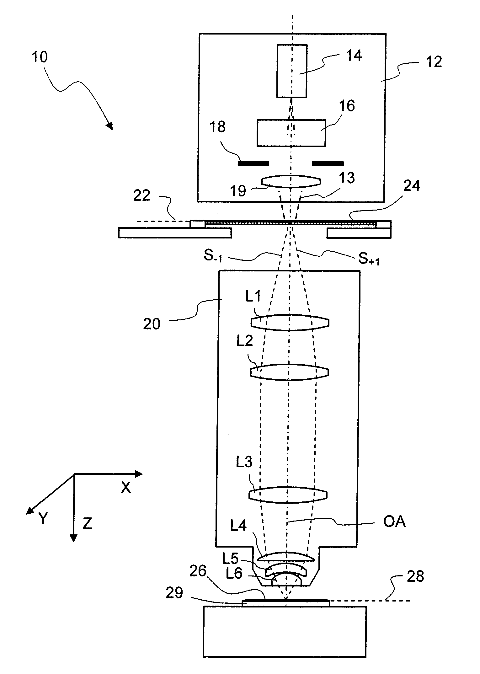
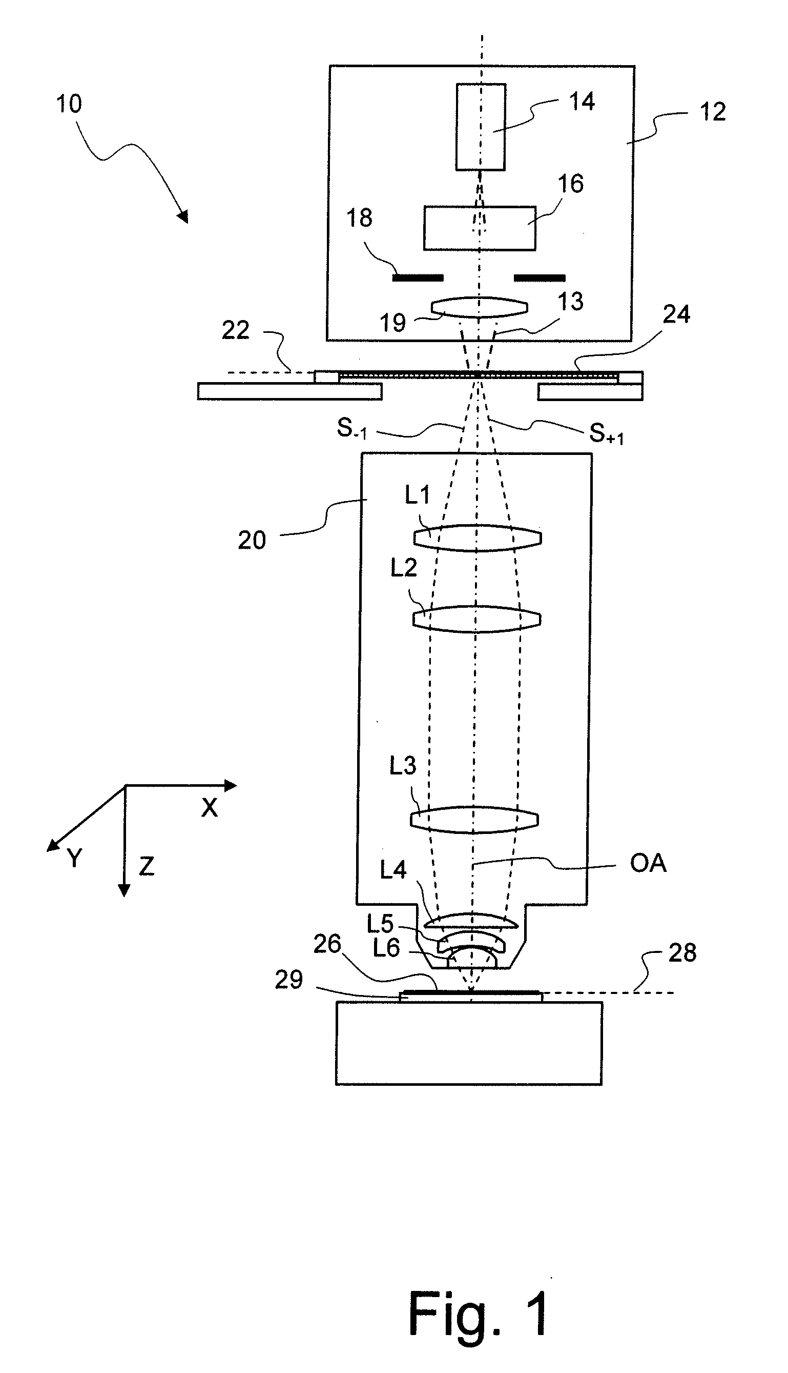
[0056]FIG. 1 shows a meridian section through a microlithographic projection exposure apparatus, denoted overall by 10, in a highly schematic representation which is not true to scale. The projection exposure apparatus 10 has an illumination system 12 for producing a projection light beam 13, which comprises a light source 14. The light source 14, which may for example be an excimer laser, produces short-wave projection light. In the present exemplary embodiment, the wavelength of the projection light is 193 nm. It is likewise possible to use other wavelengths, for example 157 nm or 248 nm.

[0057]The illumination system 12 furthermore contains illumination optics indicated by 16, and a diaphragm 18. The illumination optics 16 suitably reshape the projection light beam produced by the light source 14 and make it possible to set different illumination angle distributions. To this end, for example, the illumination device may contain interchangeable diffractive optical elements or micro...


PUM


Abstract

In a method for describing a retardation distribution of a light bundle emerging from a selected field point, which passes through a birefringent optical element contained in an optical system of a microlithographic projection exposure apparatus, a distribution of retardation vectors is determined so that precisely one direction of a retardation vector is allocated to each directionless orientation of the retardation. The retardation vector distribution is then at least approximately described as a linear superposition of predetermined vector modes with scalar superposition coefficients.

Description

CROSS-REFERENCE TO RELATED APPLICATIONS[0001]This application claims benefit of provisional application Ser. No. 60 / 641,422 filed Jan. 5, 2005. The full disclosure of this earlier application is incorporated herein by reference.BACKGROUND OF THE INVENTION[0002]1. Field of the Invention[0003]The invention relates to microlithographic projection exposure apparatus such as those used for the production of large-scale integrated electrical circuits and other microstructured components. The invention relates in particular to a method by which a retardation distribution in an exit pupil can be described for individual birefringent optical elements or optical systems formed by them in such an arrangement.[0004]2. Description of the Related Art[0005]Integrated electrical circuits and other microstructured components are conventionally produced by applying a plurality of structured layers to a suitable substrate which, for example, may be a silicon wafer. In order to structure the layers, th...

Claims


Application Information

Patent Timeline
IPC IPC(8): G02B27/28
CPCG02B5/3083G03F7/70966G03F7/70566G02B27/0025
Inventor KRAEHMER, DANIEL
Owner CARL ZEISS SMT GMBH
Why Eureka
Try Eureka