
Atmospheric pressure measuring apparatus and method of measuring atmospheric pressure

a technology of atmospheric pressure and measuring apparatus, which is applied in the direction of fluid pressure measurement, instruments, record information storage, etc., can solve the problems of sensor generation of so-called creep, deterioration of detection accuracy, and other drawbacks of conventional atmospheric pressure measuring apparatus, and achieve the effect of simplifying structur

Inactive Publication Date: 2009-08-06
KK TOSHIBA
View PDF3 Cites 9 Cited by
  • Summary
  • Abstract
  • Description
  • Claims
  • Application Information

AI Technical Summary

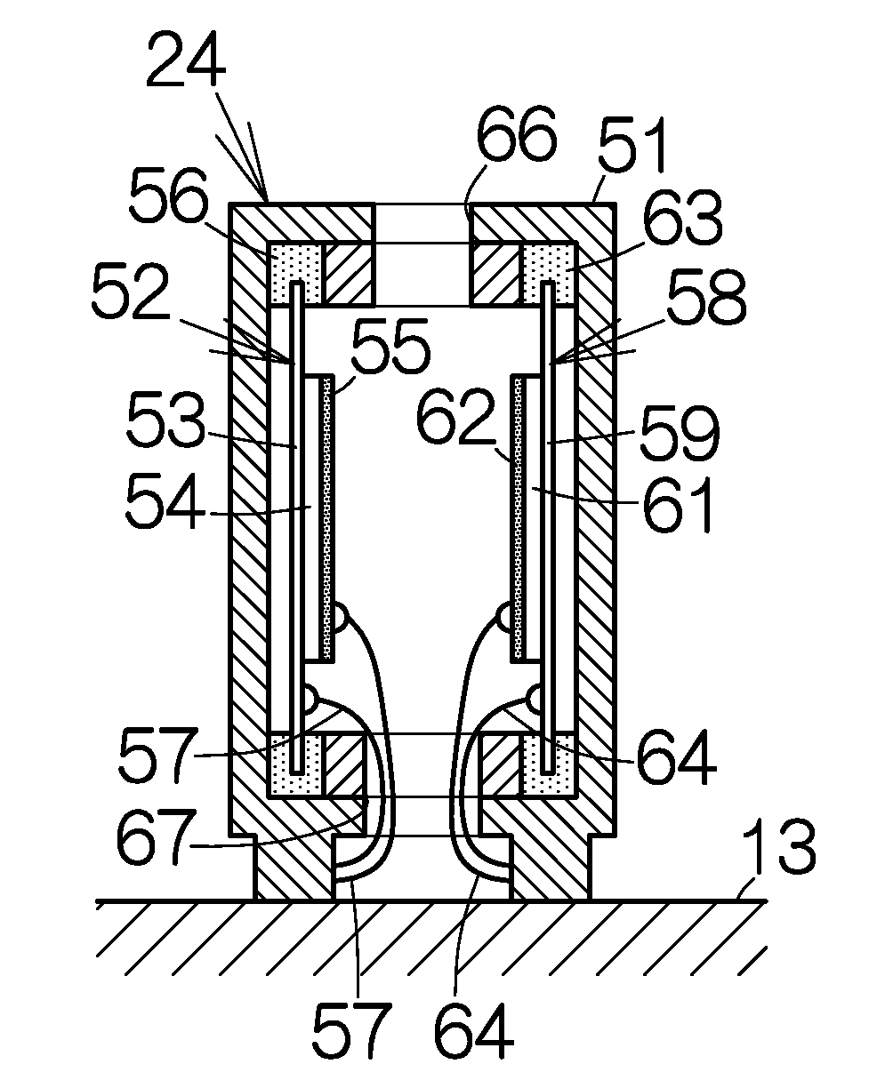
Benefits of technology

[0006]It is accordingly an object of the present invention to provide an atmospheric pressure measuring apparatus capable of detecting the atmospheric pressure with a simplified structure. It is an object of the present invention to provide a method of detecting the atmospheric pressure in a facilitated manner.
[0011]The frequency of the acoustic wave is preferably set equal to the resonant frequency of at least one of the transmitter and the receiver. The resonance of the receiver serves to increase the electric signal output from the receiver. The transmitter and the receiver are preferably spaced from each other at a distance equal to the half wavelength, of the acoustic wave transmitted from the transmitter, multiplied by an integer. This type of location enables establishment of the resonance at the receiver. The resonance of the receiver serves to increase to the utmost the electric signal output from the receiver. In particular, the frequency of the acoustic wave is preferably set in a range out of the audio frequency. Generation of noise is in this manner prevented in the atmospheric pressure measuring apparatus.
[0012]The transmitter and the receiver may each include: a diaphragm; and a piezoelectric material bonded to the diaphragm. A piezoelectric buzzer can be employed as the transmitter and the receiver. The structure of the atmospheric pressure measuring apparatus can thus be simplified. The diaphragm of the transmitter and the diaphragm of the receiver are identical in shape and dimension.
[0015]The transmitter is designed to convert an electric signal to an acoustic wave upon transmission of an acoustic wave in the method. The receiver is designed to convert an acoustic wave into an electric signal upon reception of the acoustic wave. The method may further comprise eliminating the noise of the electric signal depending on the frequency of the acoustic wave transmitted from the transmitter. The intensity of the acoustic wave is thus detected with a higher accuracy.
[0017]The frequency of the acoustic wave is preferably set equal to the resonant frequency of at least one of the transmitter and the receiver. The resonance of the receiver serves to increase the electric signal output from the receiver. The transmitter and the receiver are preferably opposed to each other at a distance equal to the half wavelength, of the acoustic wave transmitted from the transmitter, multiplied by an integer. This type of location enables establishment of the resonance at the receiver. The resonance of the receiver serves to increase to the utmost the electric signal output from the receiver. In particular, the frequency of the acoustic wave is preferably set in a range out of the audio frequency. Generation of noise is in this manner prevented in the method.
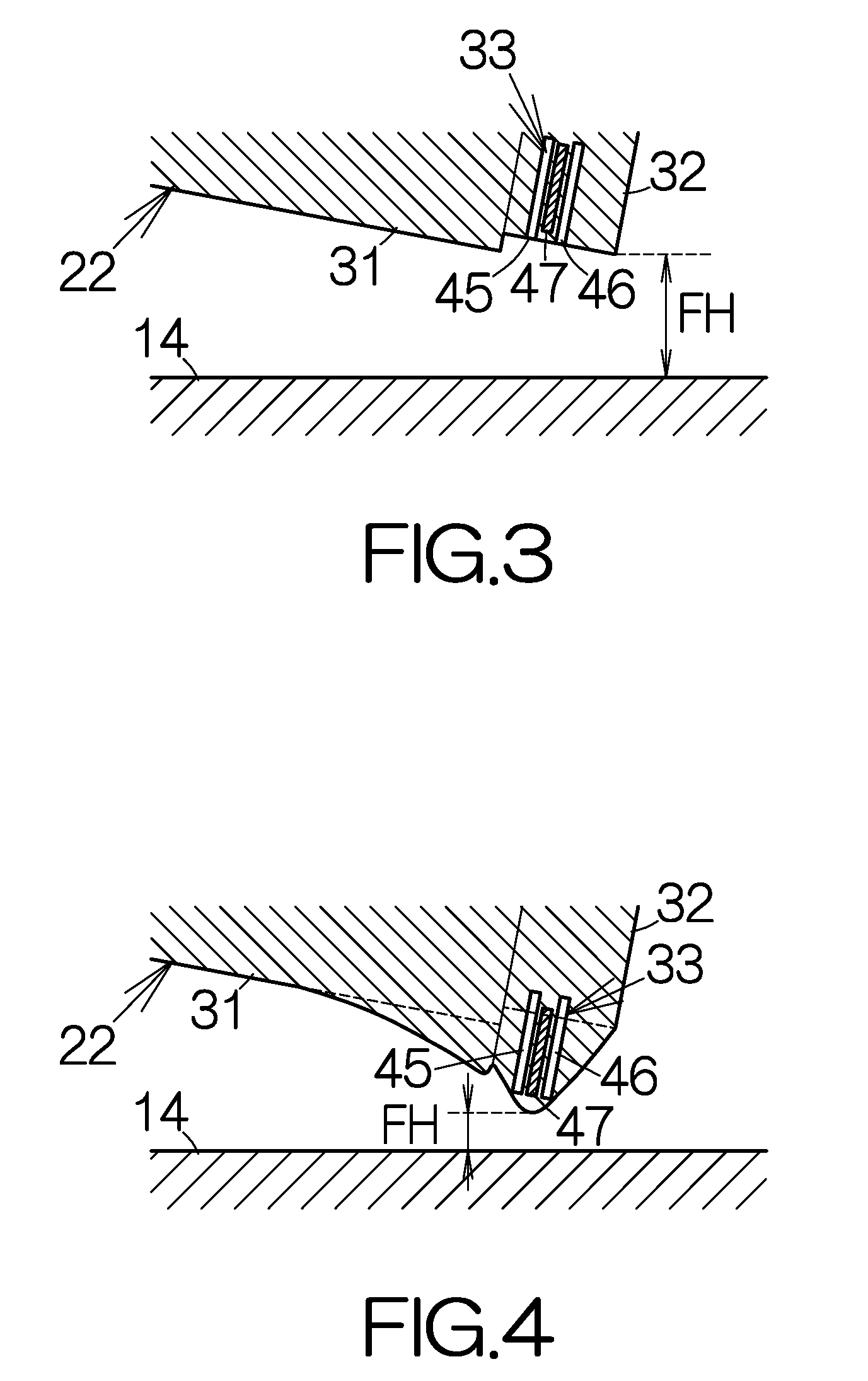
[0020]The controlling section adjusts the revolution speed of the storage medium for controlling the flying height of the head element above the storage medium. When the revolution speed increases, for example, the current of the airflow generated along the surface of the storage medium increases. The head slider is allowed to enjoy an increased positive pressure acting on the head slider. On the contrary, when the revolution speed of the storage medium decreases, the current of the airflow decreases. The head slider is thus allowed to enjoy a reduced positive pressure acting on the head slider. The adjustment of the revolution speed in this manner realizes the adjustment of the flying height of the head element.

Problems solved by technology

Accordingly, the sensor may suffer from generation of so-called creep.
This results in deterioration of the accuracy of detection.
A conventional atmospheric pressure measuring apparatus has another drawback.
This makes the atmospheric pressure measuring apparatus fragile.

Method used


Image

  • Atmospheric pressure measuring apparatus and method of measuring atmospheric pressure
  • Atmospheric pressure measuring apparatus and method of measuring atmospheric pressure
  • Atmospheric pressure measuring apparatus and method of measuring atmospheric pressure

Examples


Embodiment Construction

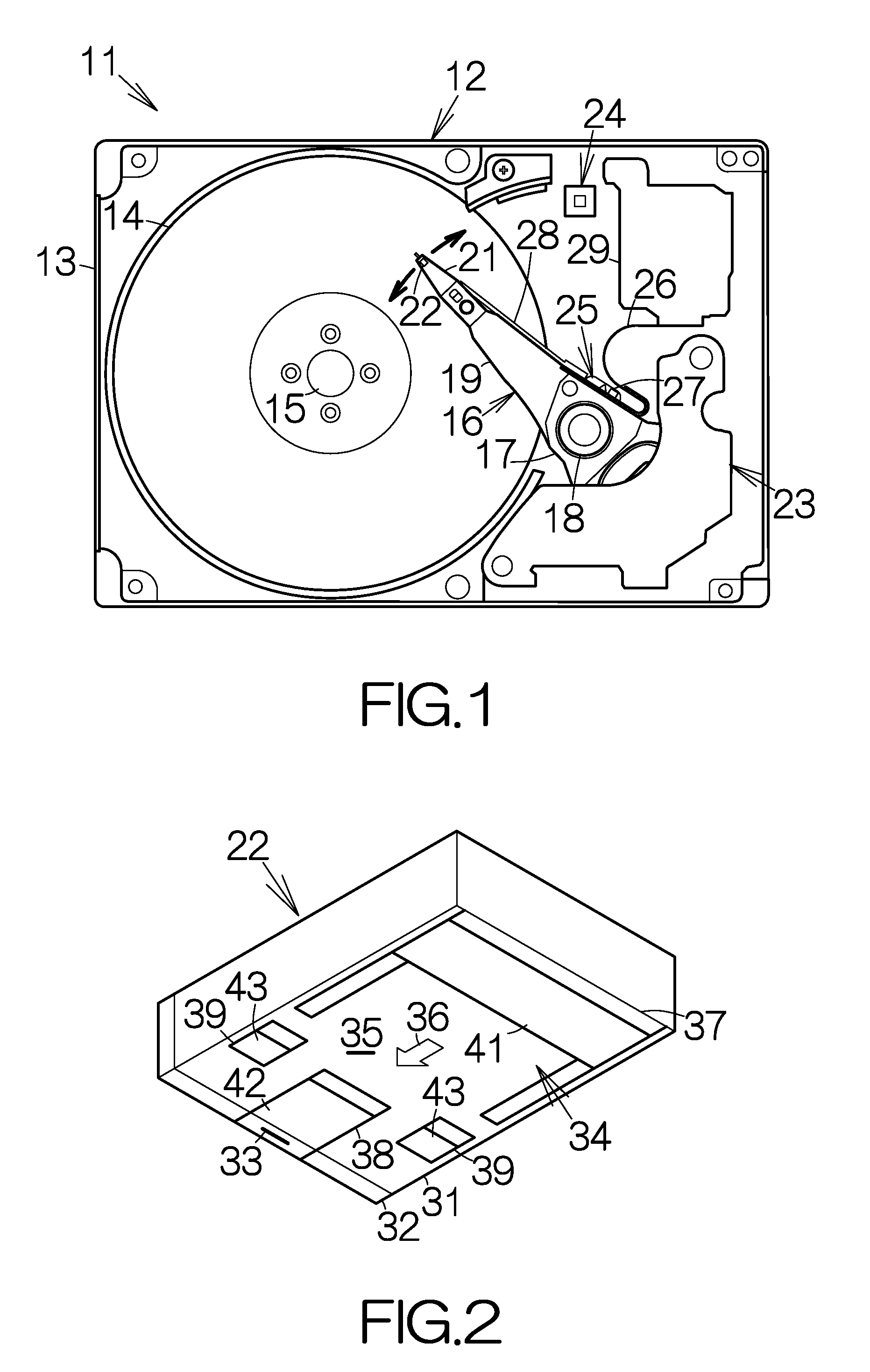
[0037]FIG. 1 schematically illustrates the inner structure of a hard disk drive, HDD, 11 as an example of a storage medium drive or storage device. The hard disk drive 11 includes an enclosure 12. The enclosure 12 includes an box-shaped enclosure base 13 and an enclosure cover, not shown. The boxed-shaped enclosure base 13 defines an inner space of a flat parallelepiped, for example. The enclosure base 13 may be made of a metallic material such as aluminum, for example. Molding process may be employed to form the enclosure base 13. The enclosure cover is coupled to the enclosure base 13. The enclosure cover serves to close the opening of the inner space of the enclosure base 13. Pressing process may be employed to form the enclosure cover out of a plate material, for example.

[0038]At least one magnetic recording disk 14 as a recording medium is incorporated within the inner space of the enclosure base 13. The magnetic recording disk or disks 14 is mounted on the driving shaft of a s...


PUM

PropertyMeasurementUnit
atmospheric pressureaaaaaaaaaa
atmospheric pressure measuring apparatusaaaaaaaaaa
atmospheric pressureaaaaaaaaaa

Abstract

An atmospheric pressure measuring apparatus allows a transmitter to transmit an acoustic wave for measurement of the atmospheric pressure. Air propagates the acoustic wave. A receiver receives the acoustic wave. Since the intensity of the acoustic wave changes to follow the variation of the atmospheric pressure, the atmospheric pressure can be measured based on the intensity of the acoustic wave received at the receiver. The atmospheric pressure is in this manner measured with such a simplified structure.

Description

BACKGROUND OF THE INVENTION[0001]1. Field of the Invention[0002]The present invention relates to an atmospheric pressure measuring apparatus and a method of measuring an atmospheric pressure.[0003]2. Description of the Prior Art[0004]An atmospheric pressure measuring apparatus includes a closed cavity with a deformable wall for detection of the absolute pressure. A sensor is placed in contact with the wall of the closed cavity. The closed cavity contains a predetermined amount of gas to hold a reference pressure therein. A variation in the atmospheric pressure around the closed cavity induces a variation in the volume of the closed cavity. The sensor is thus designed to detect the variation in the volume by sensing either the deformation or stress or strain on the wall of the closed cavity. The atmospheric pressure measuring apparatus enables detection of the atmospheric pressure based on a variation in the volume of the closed cavity.[0005]The pressure inside the closed cavity is k...

Claims


Application Information

Patent Timeline
Patent Type & Authority Applications(United States)
IPC IPC(8): G11B31/00H04B1/06
CPCG01L11/04
Inventor SUZUKI, YOSHITAKAIMAMURA, TAKAHIRO
Owner KK TOSHIBA
Learn More