
Carbon Nanohorn Carried Material And Process For Producing Carbon Nanotube

a carbon nanotube and horn technology, applied in the direction of organic compound/hydride/coordination complex catalyst, physical/chemical process catalyst, metal/metal-oxide/metal-hydroxide catalyst, etc., can solve the problems of burden and difficulty in controlling and achieve the effect of easy collection and purification of carbon nanotube and control of the length of carbon nanotub

Inactive Publication Date: 2009-08-06
NEC CORP
View PDF7 Cites 9 Cited by
  • Summary
  • Abstract
  • Description
  • Claims
  • Application Information

AI Technical Summary

Benefits of technology

[0007]With the foregoing background in view, it is an object of the present invention to solve the above described problems of the conventional technology and to provide a novel technical means for producing a carbon nanotube which does not use any noncarbon type carrier, can easily collect and purify the carbon nanotube and can control the length of the carbon nanotube.

Problems solved by technology

Thus, a burden is imposed by the recovery and refinement of carbon nanotubes, which poses a serial problem in practical application.
In conventional CVD methods, there is also a problem because it is difficult to control the length of carbon nanotubes.

Method used


Image

  • Carbon Nanohorn Carried Material And Process For Producing Carbon Nanotube
  • Carbon Nanohorn Carried Material And Process For Producing Carbon Nanotube
  • Carbon Nanohorn Carried Material And Process For Producing Carbon Nanotube

Examples


example 1

[0046]Graphite was subjected to CO2 laser ablation at room temperature in a stream of Ar (760 Torr) to prepare NHs in accordance with the method described in Chem. Phys. Lett., 1999, 309, 165. The obtained NHs were treated at 570 to 580° C. for 10 minutes in a stream of O2 to obtain carbon nanohorns (NHox) having openings in accordance with the method described in Mol. Pharm., 2005, 2, 475.

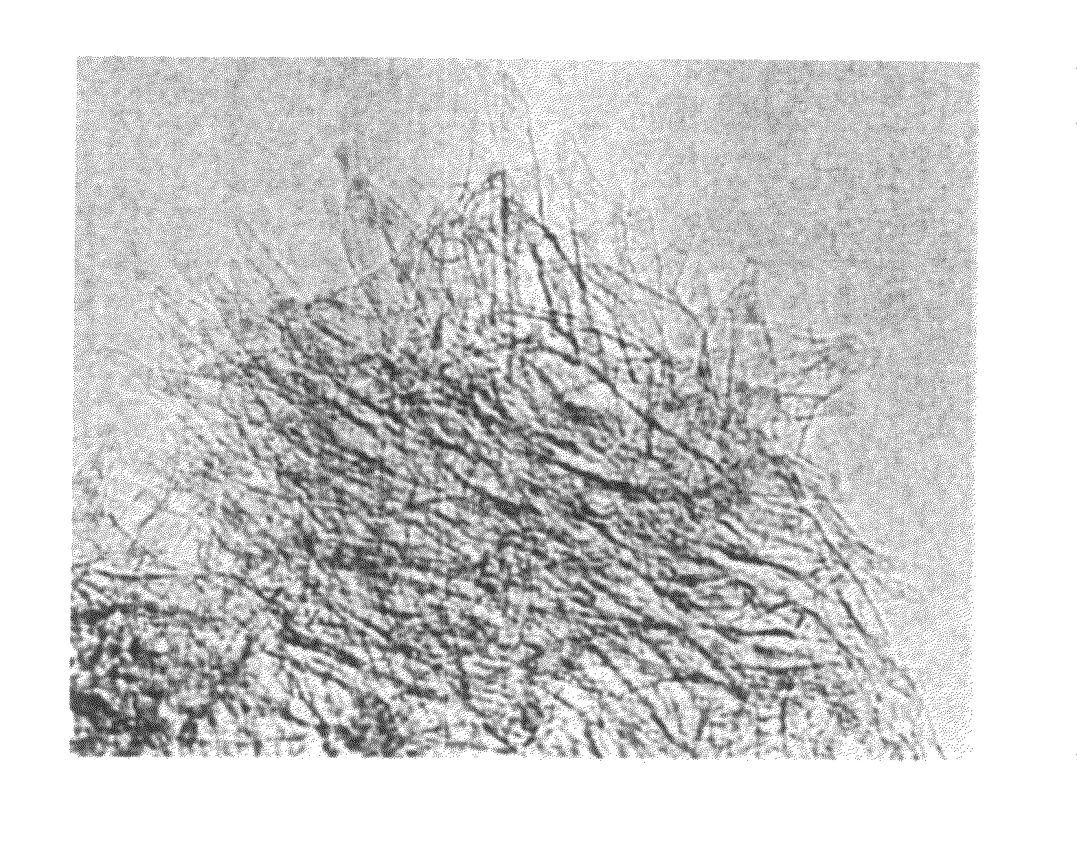
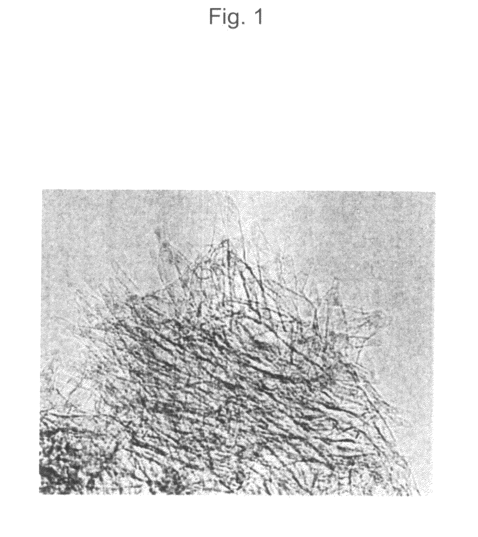
[0047]Next, 50 mg of iron acetate (manufactured by Sigma-Aldrich Inc.; purity: more than 99.995%) and 50 mg of the hole-opened nanohorns (NHox) were mixed with each other in 20 cm3 ethanol. The mixture was stirred at room temperature for 24 hours, filtered, washed with ethanol and dried to obtain iron acetate-carrying NHox having an iron content of 2 atomic %. The TEM photograph of the iron acetate-carrying NHox is shown in FIG. 1. The particles seen in NHox are those of the iron acetate.

[0048]The obtained iron acetate-carrying NHox was placed in a boat made of alumina and heated to 800° C. in a s...

example 2

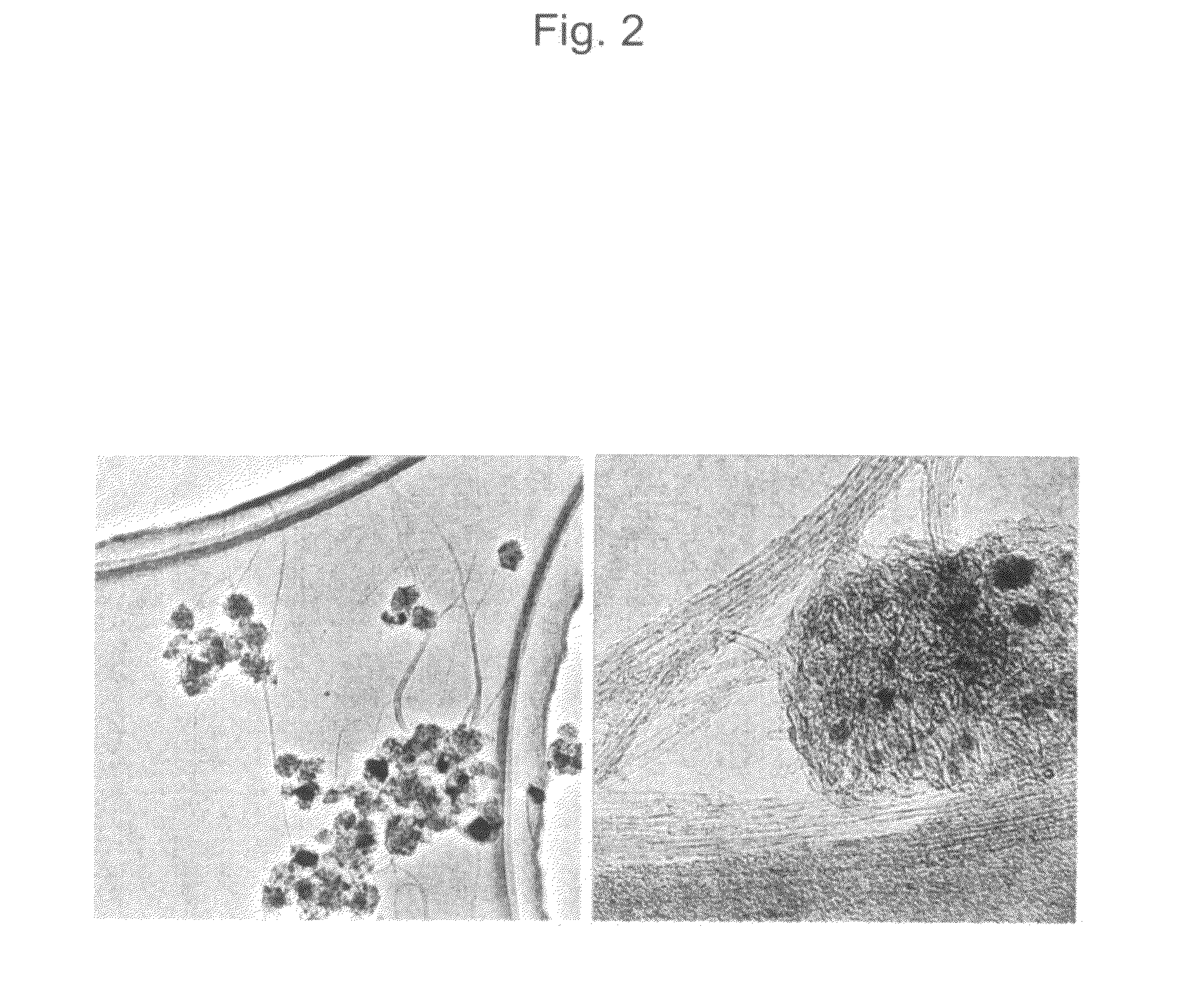
[0051]The experiment of Example 1 was conducted in the same manner as described except that nickel acetate was used in place of the iron acetate used in Example 1. The TEM photograph of the obtained multi-walled carbon nanotube (MWNT) is shown in FIG. 4. The TEM photograph of MWNT, obtained by CVD at 800° C. using carbon nanohorns containing therein nickel acetate, is seen in the observed image. In the right-side enlarged view, nickel oxide particles attached to MWNT are seen as black particles. The nickel oxide was formed by alteration of nickel acetate during the course of CVD.

example 3

[0052]The experiment of Example 1 was conducted in the same manner as described except that a mixture of cobalt acetate and molybdenum acetate (weight ratio: 1.1) was used in place of the iron acetate. The TEM photograph of the obtained double-walled carbon nanotube (DWNT) is shown in FIG. 5.


PUM

PropertyMeasurementUnit
Temperatureaaaaaaaaaa
Lengthaaaaaaaaaa
Vapor pressureaaaaaaaaaa

Abstract

A carbon nanohorn carried material for producing a carbon nanotube by a chemical vapor deposition (CVD) method, including a catalytic metal or a compound thereof contained inside carbon nanohorns or supported on exterior walls of the carbon nanohorns is provided. A carbon nanotube is produced by a CVD reaction using the carbon nanohorn carried material. A novel technical means for producing a carbon nanotube which does not use any noncarbon type carrier, can easily collect and purify the carbon nanotube and can control the length of the carbon nanotube can be provided.

Description

TECHNICAL FIELD[0001]The present invention relates to catalyst-carrying carbon nanohorns (NHs) capable of realizing a novel process for producing carbon nanotubes and to a process for producing a carbon nanohorn (NT) using the catalyst-carrying carbon nanohorns.BACKGROUND ART[0002]For the production of a carbon nanotube (NT) by a chemical vapor deposition (CVD) method, Si, SiO2, MgO, Al2O3 or the like has been hitherto used as a carrier of a catalytic metal such as Fe, Ni, Co, Pt, W and Mo. As a carbon source, an organic gas, such as methane, ethane, acetylene, benzene or an alcohol, or a CO gas is used. Such a carbon source is heated at a high temperature in the presence of the above catalyst to produce a single walled carbon nanotube (SWNT) by a CVD reaction.[0003]With the above conventional method, however, it is necessary to remove the catalyst carrier after the formation of the carbon nanotubes because the carrier is an inorganic substance other than carbon (see, for example, P...

Claims


Application Information

Patent Timeline
IPC IPC(8): C23C16/00B01J21/18B01J23/02B01J23/42B01J23/74B01J31/12
CPCB01J21/185Y10T428/2991B01J23/42B01J23/74B01J23/745B01J37/0207B82Y30/00B82Y40/00C01B31/0233C01B2202/02C01B2202/04C01B2202/06C01P2004/13Y10S977/773B01J23/24C01B32/162
Inventor IIJIMA, SUMIOYUDASAKA, MASAKOMIYAWAKI, JIN
Owner NEC CORP
Learn More