Recording apparatus, recording method, program for recording method, and storage medium that stores program for recording method
a recording method and program technology, applied in the field of recording apparatus, can solve the problems of reducing the serviceable life of flash memory and general limitation of the number of recording operations of flash memory, and achieve the effect of suppressing a significant reduction in the serviceable life of storage media
- Summary
- Abstract
- Description
- Claims
- Application Information
AI Technical Summary
Benefits of technology
Problems solved by technology
Method used
Image
Examples
first embodiment
(1) Configuration of Embodiment
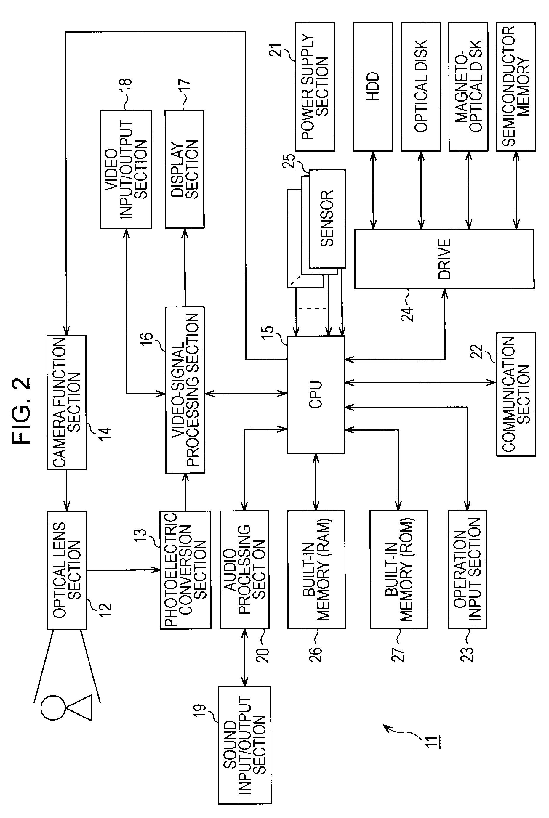
[0054]FIG. 2 is a block diagram showing a digital video camera that serves as a recording apparatus according to a first embodiment of the present invention. In this digital video camera 11, an optical lens section 12 forms a subject's optical image on an image-capture surface of a photoelectric conversion section 13. Under the control of a central processing unit (CPU) 15, a camera function section 14 controls changes in a focal distance and a diaphragm of the optical lens section 12. The photoelectric conversion section 13 has, for example, a CMOS (complementary metal oxide semiconductor) solid-state image capture device, a CCD (charge coupled device) solid-state image capture device, or the like, and outputs a photoelectric conversion result of the optical image.
[0055]A video-signal processing section 16 processes a signal output from the photoelectric conversion section 13 to generate video data and outputs the video data to a display section 17 an...
second embodiment
[0137]FIG. 13 is a flowchart showing, in comparison with FIGS. 4 and 5, a processing procedure for a device driver layer of a digital video camera according to a second embodiment of the present invention. The digital video camera according to the second embodiment has the same configuration as that of the above-described first embodiment, except that an arrangement for the processing procedure for the device driver layer is different.
[0138]Under the control of the application layer via the file system layer, the device driver layer in the second embodiment dynamically switches processing for the cache. Thus, the processing procedure includes steps SP61 and SP62 for processing for switching use of the cache.
[0139]Thus, a case in which the device driver layer dynamically switches processing for the cache, as in the present embodiment, can also provides the same advantages as the above-described first embodiment.
third embodiment
[0140]FIG. 14 is a block diagram showing a computer that serves as a recording apparatus according to a third embodiment of the present invention. A computer 51 includes a CPU 52, a built-in RAM 53, and a built-in ROM 54, which are interconnected through a bus. Various interfaces are also connected to the bus via an input / output interface 55, which serves as a device controller. The interfaces for the computer 51 include an input section 56, an output section 57, a communication section 58, and an auxiliary storage section 59. Examples of the input section 56 include a keyboard, a mouse, a scanner, and a microphone. Examples of the output section 57 include a display, a speaker, a printer, and a plotter. Examples of the communication section 58 include a USB interface, an IEEE 1394 interface, a Bluetooth interface, and an IEEE 802.11a / b / g interface. Examples of the auxiliary storage section 59 include an optical disk, a magnetic disk, a magneto-optical disk, and a semiconductor memo...
PUM
 Abstract
Description
Claims
Application Information
 - R&D
- Intellectual Property
- Life Sciences
- Materials
- Tech Scout
- Unparalleled Data Quality
- Higher Quality Content
- 60% Fewer Hallucinations
Browse by: Latest US Patents, China's latest patents, Technical Efficacy Thesaurus, Application Domain, Technology Topic, Popular Technical Reports.
© 2025 PatSnap. All rights reserved.Legal|Privacy policy|Modern Slavery Act Transparency Statement|Sitemap|About US| Contact US: help@patsnap.com


