
Masked laser anneal during fabrication of backside illuminated image sensors

Active Publication Date: 2009-08-13
OMNIVISION TECH INC
View PDF7 Cites 55 Cited by
  • Summary
  • Abstract
  • Description
  • Claims
  • Application Information

AI Technical Summary

Problems solved by technology

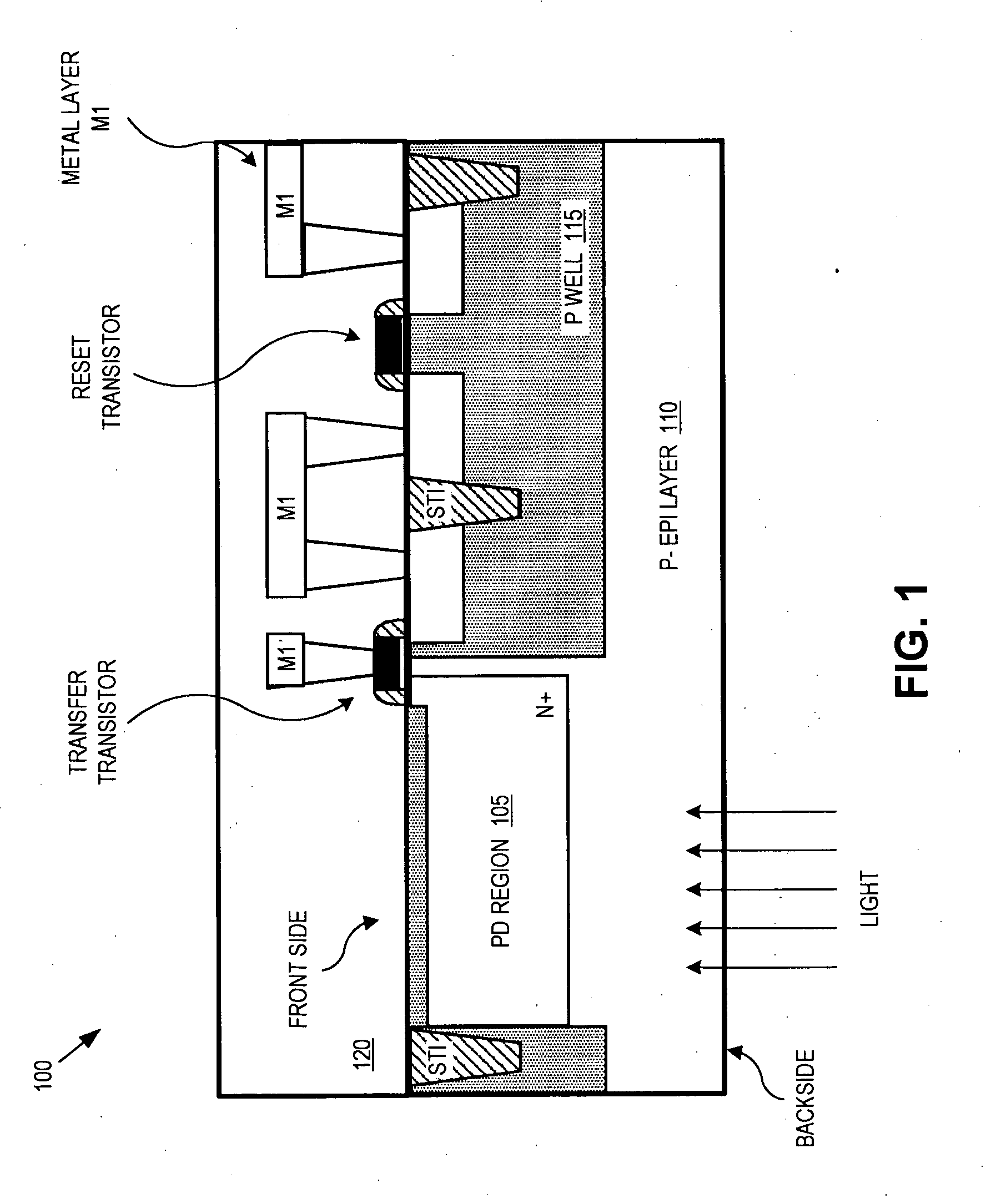
However, when the silicon is thin (e.g., P− epi layer 110120 and the remainder of the back-end-of-the-line (“BEOL”) may cause a significant increase in substrate temperature that can result in deleterious effects, such as dopant diffusion at temperatures greater than 800 C and / or BEOL metal deterioration / melting at temperatures greater than 400 C.
However, increasing this thickness results in increased electrical crosstalk between adjacent pixels in an imaging sensor array.

Method used


Image

  • Masked laser anneal during fabrication of backside illuminated image sensors
  • Masked laser anneal during fabrication of backside illuminated image sensors
  • Masked laser anneal during fabrication of backside illuminated image sensors

Examples


Embodiment Construction

[0018]Embodiments of a system and method for fabricating a backside illuminated (“BSI”) imaging sensor are described herein. In the following description numerous specific details are set forth to provide a thorough understanding of the embodiments. One skilled in the relevant art will recognize, however, that the techniques described herein can be practiced without one or more of the specific details, or with other methods, components, materials, etc. In other instances, well-known structures, materials, or operations are not shown or described in detail to avoid obscuring certain aspects.

[0019]Reference throughout this specification to “one embodiment” or “an embodiment” means that a particular feature, structure, or characteristic described in connection with the embodiment is included in at least one embodiment of the present invention. Thus, the appearances of the phrases “in one embodiment” or “in an embodiment” in various places throughout this specification are not necessari...


PUM


Abstract

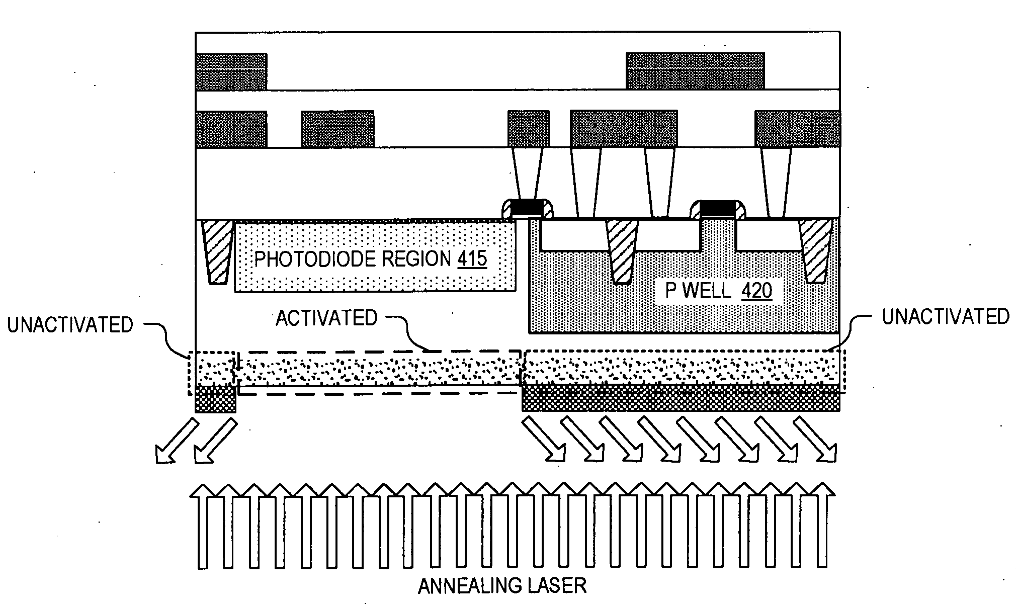
A technique for fabricating an array of imaging pixels includes fabricating front side components on a front side of the array. After fabricating the front side components, a dopant layer is implanted on a backside of the array. A mask is formed over the dopant layer to selectively expose portions of the dopant layer. Next, the exposed portions of the dopant layer are laser annealed. Alternatively, the mask may be disposed over the backside prior to the formation of the dopant layer and the dopants implanted through the exposed portions and subsequently laser annealed.

Description

CROSS REFERENCE TO RELATED APPLICATION[0001]This application claims the benefit of U.S. Provisional Application No. 61 / 027,362, filed on Feb. 8, 2008, the contents of which are incorporated herein by reference.TECHNICAL FIELD[0002]This disclosure relates generally to imaging sensors, and in particular but not exclusively, relates to backside illuminated CMOS imaging sensors.BACKGROUND INFORMATION[0003]FIG. 1 illustrates a backside illuminated (“BSI”) image sensor 100 including a photodiode (“PD”) region 105 disposed within a silicon P− epitaxial (“epi”) layer 110. Pixel circuitry for operation of the BSI image sensor is formed over a P well 115. Only the transfer transistor and the reset transistor of the pixel circuitry are illustrated. A first metal layer M1 for coupling to the gates of the transfer and reset transistors is disposed within an inter-metal dielectric layer 120.[0004]BSI image sensor 100 is photosensitive to light incident upon the backside of the sensor die. For BSI...

Claims


Application Information

Patent Timeline
IPC IPC(8): H01L33/00H01L21/00
CPCH01L27/14687Y10S438/949H01L27/1464
Inventor VENEZIA, VINCENTTAI, HSIN-CHIHMAO, DULIQIAN, YIN
Owner OMNIVISION TECH INC
Learn More