
Utilities supply member connection apparatus, stage apparatus, projection optical system support apparatus and exposure apparatus

Inactive Publication Date: 2009-08-13
NIKON CORP
View PDF17 Cites 26 Cited by
  • Summary
  • Abstract
  • Description
  • Claims
  • Application Information

AI Technical Summary

Benefits of technology

[0017]Therefore, in the first aspect, in a case in which a slight displacement difference has occurred between the first member and the second member, a slight displacement difference is produced between the holding part, which holds the utilities supply member, and the second member, but by measuring this slight displacement difference by means of the measuring apparatus and driving the holding part by an amount of movement that would correct the aforementioned slight displacement difference via the drive apparatus by means of the control apparatus, it is possible to set the relative displacement of the holding part and the second member to zero to maintain the relative positional relationship of these in a fixed status. For this reason, stress attributable to a slight displacement difference produced between the first member and the second member is not produced in the utilities supply member positioned between the holding part and the second member, and it is possible to restrict adverse influences that the stress has on the second member. In addition, in the first aspect, the reaction force at the time of driving of the holding part is not transmitted to the second member; for example, in the case in which the drive apparatus has been provided on the first member, said first member bears the load, and this reaction force can be restricted from having an adverse influence on the second member.
[0021]Therefore, in the third aspect, in the case in which a slight displacement difference is produced between the movable stage and the substage, it is possible to set the relative displacement between the holding part and the movable stage to zero to maintain the relative positional relationship of these in a fixed status. For this reason, stress attributable to a slight displacement difference produced between the movable stage and the substage is not produced in the utilities supply member positioned between the holding part and the movable stage, and it is possible to restrict this stress from exerting adverse influence upon the movement characteristics of the movable stage.
[0025]Therefore, in the fifth aspect, it is possible to restrict adverse influences from being exerted upon the movement characteristics of the movable stage and the projection characteristics of the projection optical system, and it is possible to realize high accuracy exposure processing.
[0026]According to some aspects of the present invention, it is possible to restrict adverse influences attributable to the presence of a utilities supply member.

Problems solved by technology

In addition, since all of the mechanical structures mechanically resonate with respect to vibration of a prescribed frequency, when such a vibration was transmitted to that structural body, there were drawbacks in that deformation of the structural body or resonance phenomena were caused, and positional misalignment of the transfer pattern or a decrease in contrast occurred.
However, problems such as those below are present in the prior art discussed above.
For that reason, as discussed above, even if a configuration in which vibrations transmitted to the projection optical system are suppressed by supporting the projection optical system in a suspended manner were to be employed, there would be a possibility of stress resulting from a slight displacement difference produced between the support member and the frame being transmitted via a utilities supply member.
In addition, there is also a possibility that external disturbances such as floor vibration, etc. would be transmitted to the support member via the utilities supply member, thereby producing stress.
In the case in which stress attributable to the presence of the utilities supply member has unfortunately slightly deformed the body and has caused the interferometer system (measuring system) to vibrate, stage accuracy (the position information measurement accuracy of a substrate such as a wafer held by the stage) will unfortunately deteriorate.
The accuracy required of exposure apparatuses is becoming higher year by year, and the effects of stress attributable to the presence of the utilities supply members can no longer be ignored.

Method used


Image

  • Utilities supply member connection apparatus, stage apparatus, projection optical system support apparatus and exposure apparatus
  • Utilities supply member connection apparatus, stage apparatus, projection optical system support apparatus and exposure apparatus
  • Utilities supply member connection apparatus, stage apparatus, projection optical system support apparatus and exposure apparatus

Examples


first embodiment

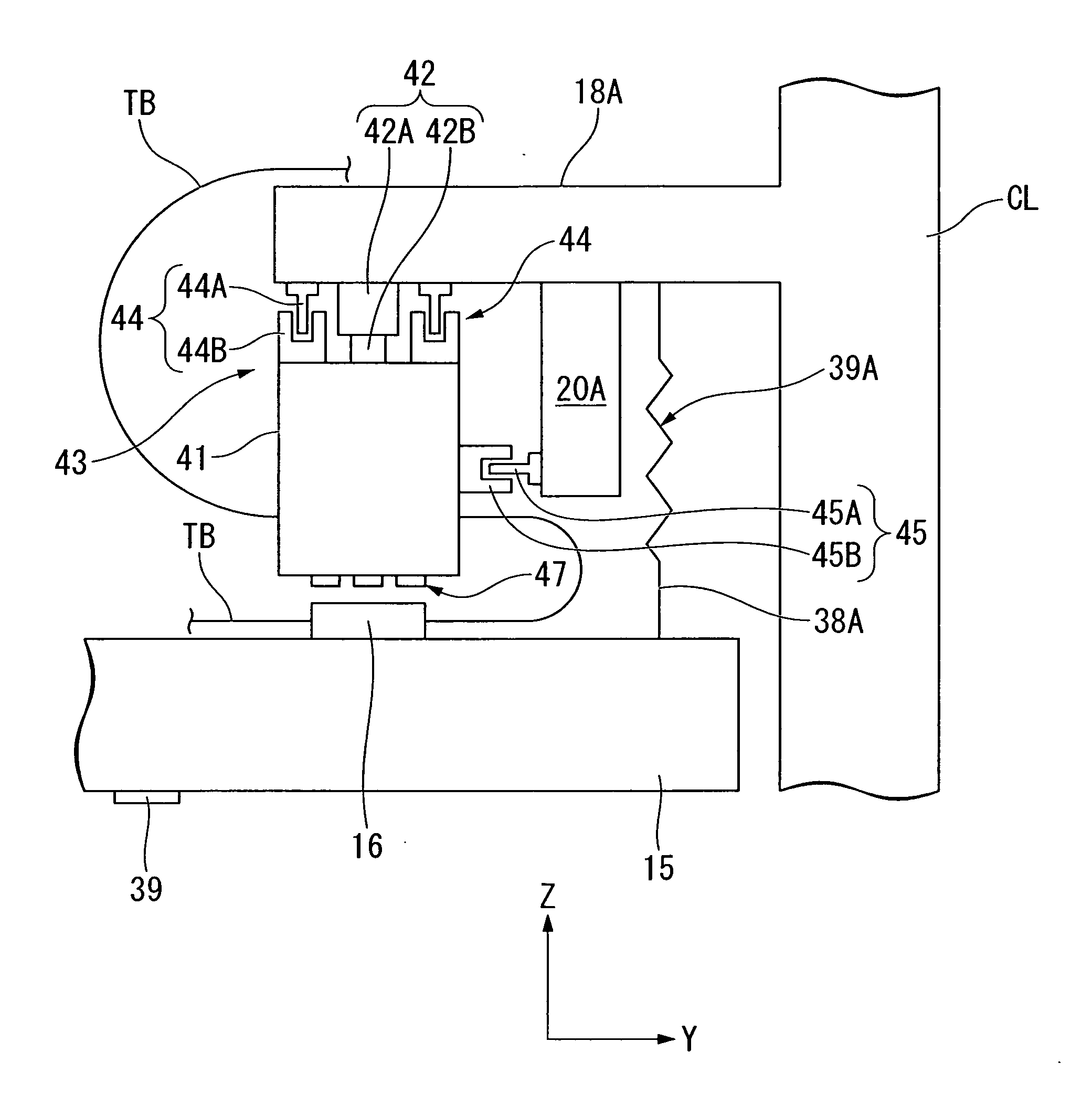
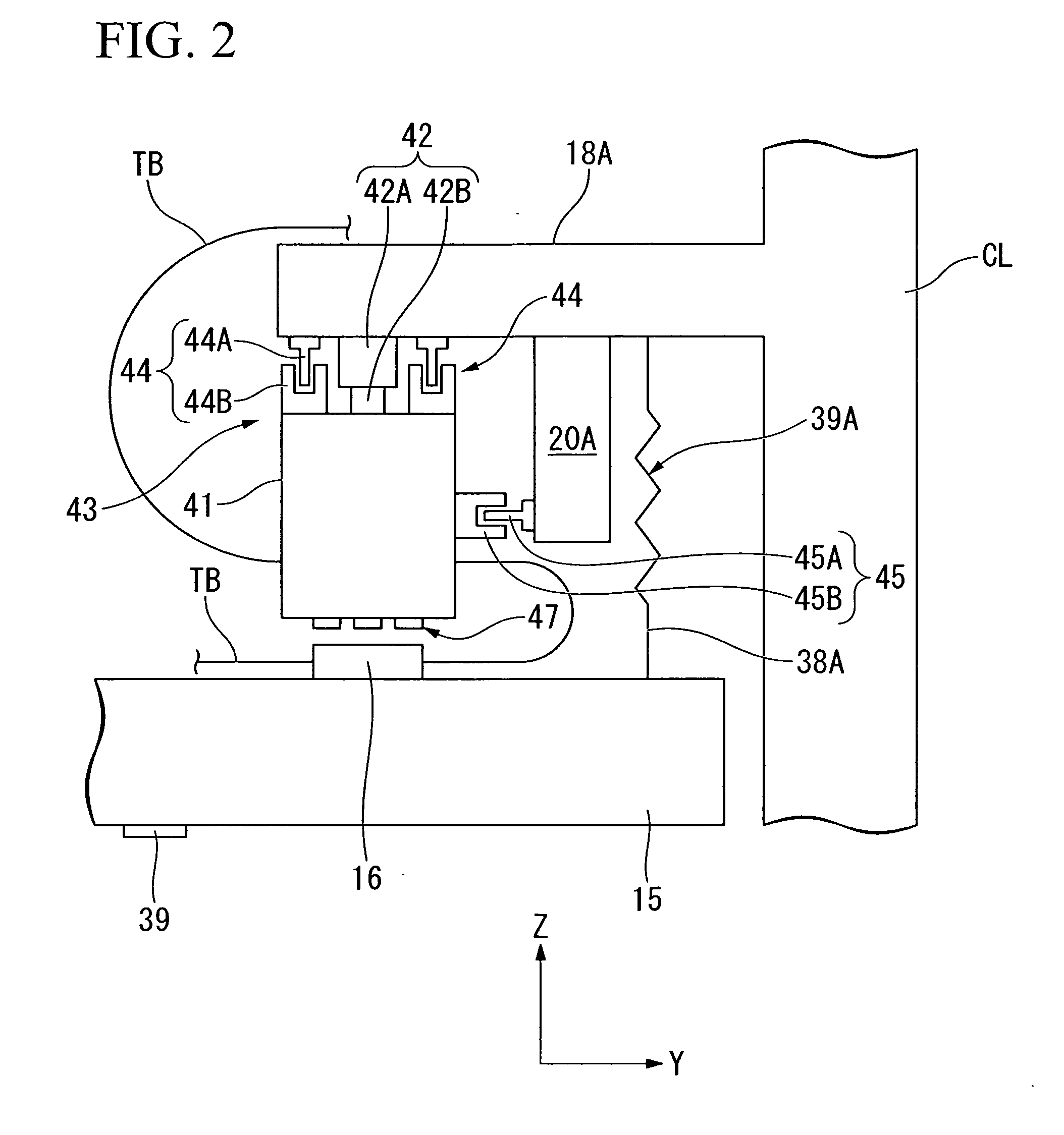
[0037]In the present embodiment, a description will be given regarding a utilities supply member connection apparatus relating to the present invention applied to a utilities supply member connected between a metrology frame, which supports a projection optical system in an exposure apparatus, and a main body column.

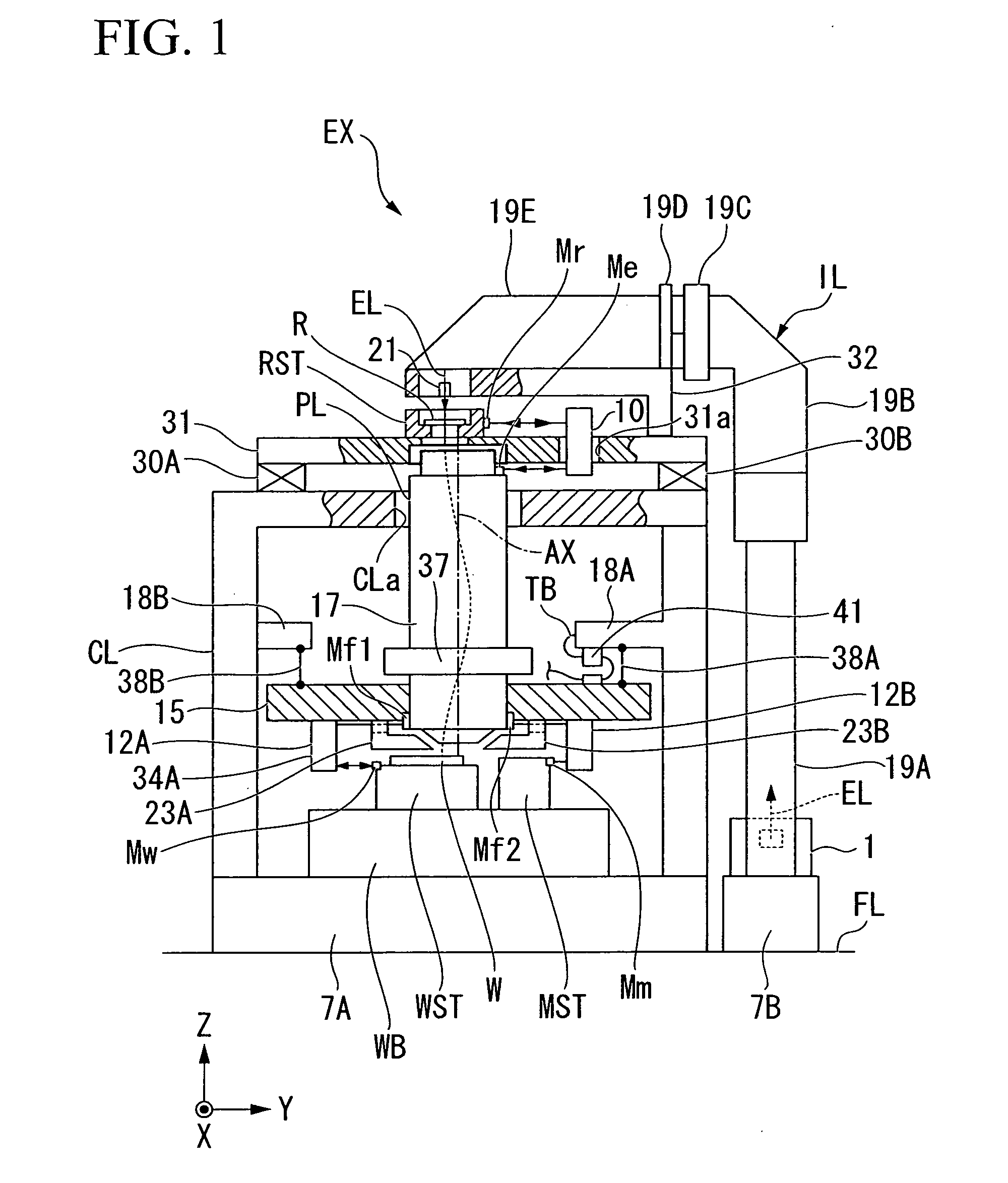
[0038]FIG. 1 is a drawing that shows the schematic configuration of an exposure apparatus EX relating to the first embodiment of the present invention.

[0039]The exposure apparatus EX shown in this drawing is a step-and-scan system scanning type exposure apparatus, specifically, a scanning stepper, that synchronously moves a reticle R and a wafer W in a one-dimensional direction while transferring a pattern formed on the reticle R onto the respective shot regions on the wafer W.

[0040]In the description below, if necessary, an XYZ rectangular coordinate system will be set up in the drawing, and the positional relationships of the respective members will be described while ...

second embodiment

[0070]Next, a second embodiment will be described while referring to FIG. 4.

[0071]Note that, in this figure, identical symbols are assigned to elements that are identical to the constituent elements of the first embodiment shown in FIG. 1 through FIG. 3, and descriptions thereof are omitted.

[0072]In the above first embodiment, the configuration was such that the utilities supply member TB was directly connected from the main body column CL to the holding member 41, but, in the present embodiment, a description will be given with respect to a configuration in which connection to the holding member 41 is performed via a mass apparatus.

[0073]As shown in FIG. 4, in the present embodiment, a mass apparatus MD is provided on frame 18A. This mass apparatus MD comprises an elastic body 51, which has low rigidity and is provided on frame 18A as the main body part, and a mass body 52 connected to frame 18A via the elastic body 51. The mass body 52 is connected to a utilities supply member TB ...

third embodiment

[0079]Next, a third embodiment will be described while referring to FIG. 5.

[0080]Note that, in this figure, identical symbols are assigned to elements that are identical to the constituent elements of the first embodiment shown in FIG. 1 through FIG. 3, and descriptions thereof are omitted.

[0081]In the above first embodiment, the configuration was such that the holding member 41 was supported by the dead load support part 42, but, in the present embodiment, an elastic member (in the present embodiment, a coil spring) 48 that has low rigidity is used as the support apparatus to support the holding member 41 to freely move with six degrees of freedom.

[0082]This coil spring 48 is such that one end is supported by frame 18A, and the other end is connected to the support member 41, and the rigidity (spring constant) is set so that it is possible to support the dead load of the holding member 41 and so that the characteristic frequency (frequency) of a vibration system formed by said coil...


PUM


Abstract

A connection apparatus for a utilities supply member, comprises: a holding part (41), a drive apparatus (43), a measuring apparatus (47), and a control apparatus. The holding part (41) is supported to freely move relative to a first member (CL) and holds a part of a utilities supply member (TB) connected between the first member (CL) and a second member (15). The drive apparatus moves the holding part (41) relative to the first member (CL). A measuring apparatus (47) obtains information relating to the relative position between the holding part (41) and the second member (15). The control apparatus controls the drive apparatus (43) based on the measurement results of the measuring apparatus (47).

Description

CROSS-REFERENCE TO RELATED APPLICATION[0001]This application is a non-provisional application claiming priority to and the benefit of U.S. provisional application No. 60 / 996,237, filed Nov. 7, 2007, and claims priority to Japanese Patent Application No. 2007-280623, filed Oct. 29, 2007. The entire contents of which are incorporated herein by reference.BACKGROUND[0002]1. Field of the Invention[0003]The present invention relates to a utilities supply member connection apparatus, a stage apparatus, a projection optical system support apparatus, and an exposure apparatus.[0004]2. Related Art[0005]In manufacturing semiconductor devices, etc., a projection exposure apparatus that transfers the image of the pattern of a reticle as a mask to the respective shot regions on a wafer (or a glass plate, etc.) that has been coated with a resist as a substrate via a projection optical system is used. Conventionally, step-and-repeat system (full-field exposure type) projection exposure apparatuses ...

Claims


Application Information

Patent Timeline
IPC IPC(8): G03B27/58
CPCB82Y10/00B82Y40/00F16F7/104G03F7/70991G03F7/70833G03F7/709G03F7/0002
Inventor ARAI, DAI
Owner NIKON CORP
Features
  • Generate Ideas
  • Intellectual Property
  • Life Sciences
  • Materials
  • Tech Scout
  • Unparalleled Data Quality
  • Higher Quality Content
  • 60% Fewer Hallucinations
Learn More