Energy Conversion Device

Inactive Publication Date: 2009-08-20
TEMPRONICS INC
View PDF44 Cites 34 Cited by
  • Summary
  • Abstract
  • Description
  • Claims
  • Application Information

AI Technical Summary

Benefits of technology

[0023]The present disclosure provides improvements in the packaging, fabrication, and more specific implementation detail of the gap-forming designs described in PCT/US07/77042. Four package design approaches are presented, each trading off cost and reliability uniquely. The first and preferred package design uses flexible glass and flexible silicon to serve simultaneously as the vacuum wall, the electrode substrate, and optionally the circuit board for interconnect. The s

Problems solved by technology

The third package design employs a flexible plastic material that is a vacuum-compatible offering lower cost, but less relia

Method used


Image

  • Energy Conversion Device
  • Energy Conversion Device
  • Energy Conversion Device

Examples


Embodiment Construction

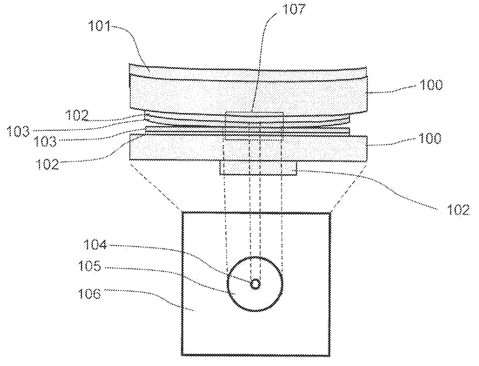
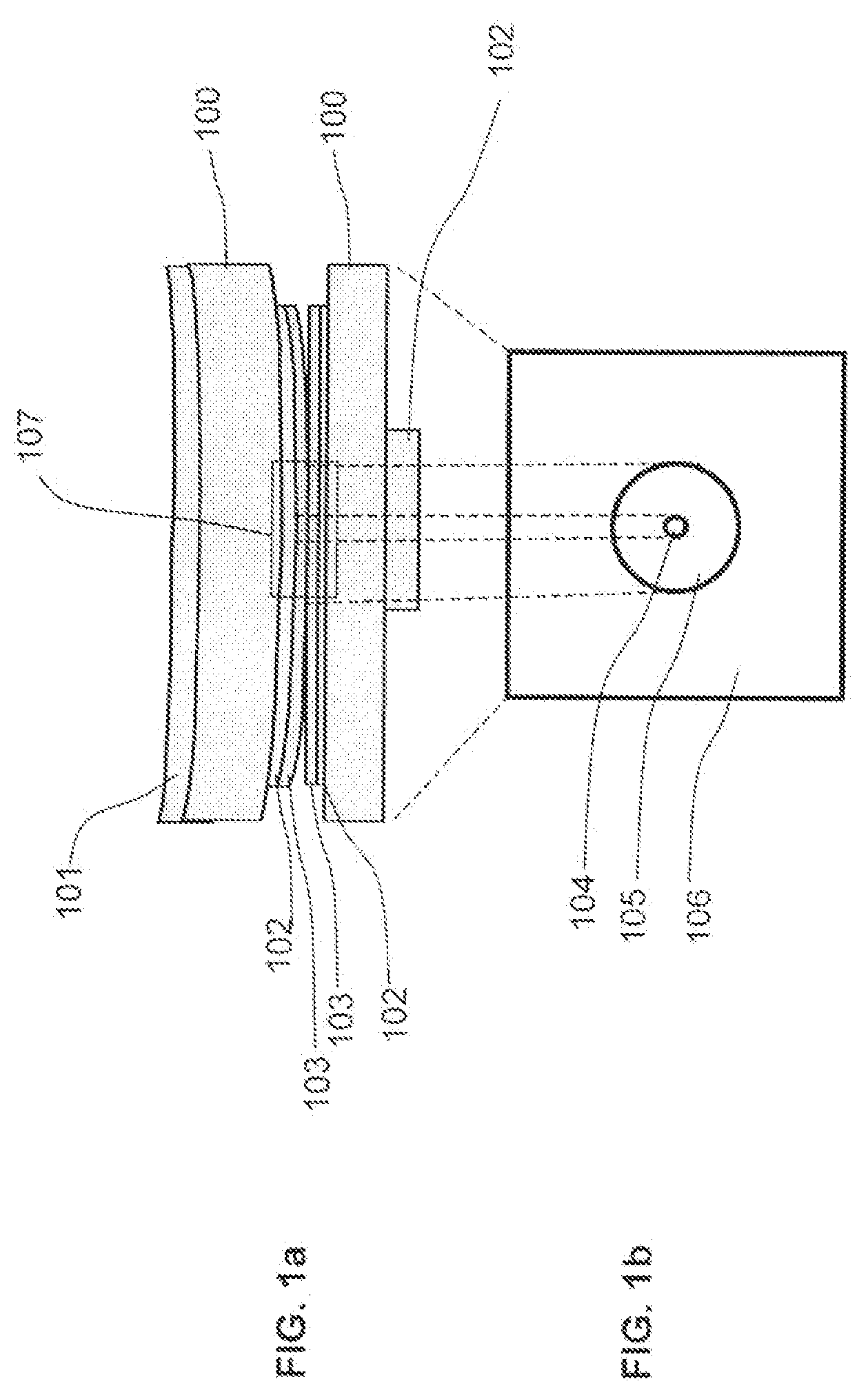
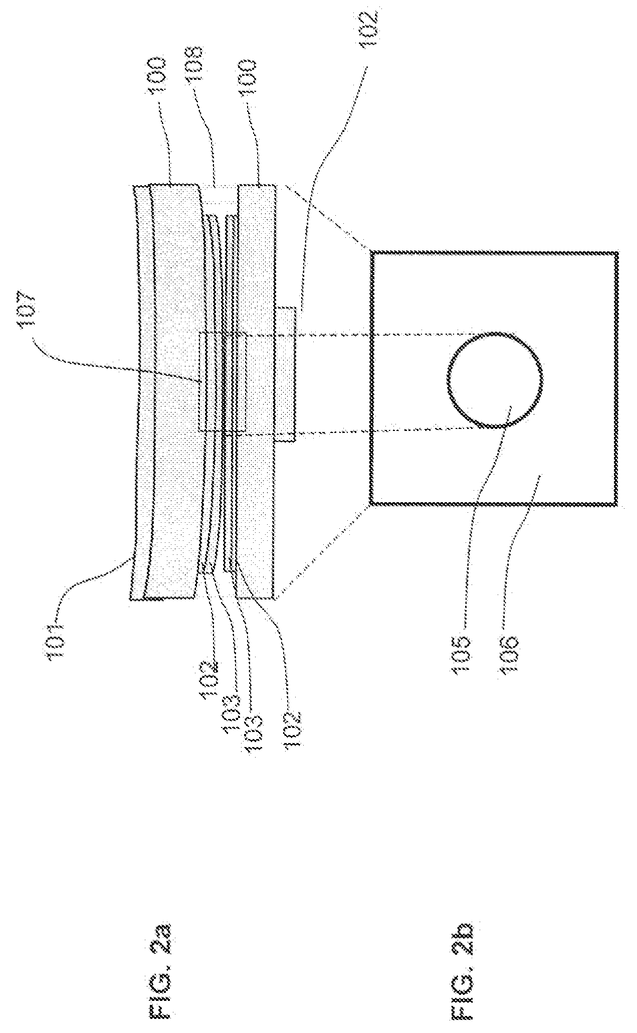
[0043]Referring more specifically to the drawings in which like reference numerals refer to like elements throughout the several views, exemplary embodiments of the device and process of the present disclosure are illustrated in FIGS. 1-12.

[0044]In FIG. 1a, two electrodes are shown, one curved and the other essentially flat. A piece of single-crystal silicon 100 serves as the substrate, and this substrate is highly doped to levels of 0.001 to 0.01 ohm-cm to allow electrical conductivity from top to bottom. Without limitation, other semiconductors could be used for substrate 100 such as silicon carbide, germanium, and gallium arsenide. Both types of metal layers 101 and 102 serve to spread the electrical current allowing this current to flow across the entire area of the silicon substrate 100, thereby reducing resistance of current flow from the top of the device to the bottom. Metal layer 101 is thicker, or laterally larger, or both thicker and laterally larger than metal layer 102....


PUM


Abstract

An improved design for maintaining nanometer separation between electrodes in tunneling, thermo-tunneling, diode, thermionic, thermoelectric, thermo-photovoltaic and other devices is disclosed. At least one electrode is of a curved shape. All embodiments reduce the thermal conduction between the two electrodes when compared to the prior art. Some embodiments provide a large tunneling area surrounding a small contact area. Other embodiments remove the contact area completely. The end result is an electronic device that maintains two closely spaced parallel electrodes in stable equilibrium with a nanometer gap there-between over a large area in a simple configuration for simplified manufacturability and use to convert heat to electricity or electricity to cooling.

Description

CROSS REFERENCE TO RELATED APPLICATION[0001]This application claims priority from U.S. Provisional Application Ser. No. 61 / 065,915, filed Feb. 15, 2008, the contents of which are incorporated by reference.BACKGROUND[0002]The present invention pertains to diode, thermionic, tunneling, and other devices that are designed to have very small spacing between electrodes and in some cases also require thermal isolation between electrodes. The invention may be applied to thermo-tunneling generators and heat pumps, and can be applied to similar systems using thermionic and thermoelectric methods. These thermo-tunneling generators and heat pumps convert thermal energy into electrical energy and can operate in reverse to provide refrigeration. The invention may also be applied to any device that requires close, parallel spacing of two electrodes with a voltage applied or generated between them.[0003]The phenomenon of high-energy electron flow from one conductor (emitter) to another conductor (...

Claims


Application Information

Patent Timeline
IPC IPC(8): H01L35/34H01L35/20H01L35/16
CPCH01L35/32H01J45/00H10N10/17
Inventor MAKANSI, TAREK
Owner TEMPRONICS INC
Why Eureka
Try Eureka