Method And Apparatus For The Manipulation And/Or The Detection Of Particles

Active Publication Date: 2009-08-20
MENARINI SILICON BIOSYSTEMS SPA
View PDF65 Cites 31 Cited by
  • Summary
  • Abstract
  • Description
  • Claims
  • Application Information

AI Technical Summary

Benefits of technology

[0018]The object of the present invention is also a family of apparatuses for identification and/or quantification and/or characterization of particles by means of impedance meter and/or optical sensors. The combination of sensors and actuators is particularly useful for automati

Problems solved by technology

There follows an important limitation due to the dimensions of each trap, limited by the need to integrate in the space corresponding to an individual electrode the electronics necessary for programming.
There follows an important limitation due to the impossibility in the independent manipulation of individual particles.
Other methods for the manipulation of particles based upon dielectrophoresis do not enable independent control on a multiplicity of particles, as described by T. Schnelle et al., Biochim. Biophys. Acta 1157, 127-140 (1993).
There follows an important limitation in the applications that require the study of the interaction between a multiplicity of cells.
In addition to the

Method used


Image

  • Method And Apparatus For The Manipulation And/Or The Detection Of Particles
  • Method And Apparatus For The Manipulation And/Or The Detection Of Particles
  • Method And Apparatus For The Manipulation And/Or The Detection Of Particles

Examples


first embodiment

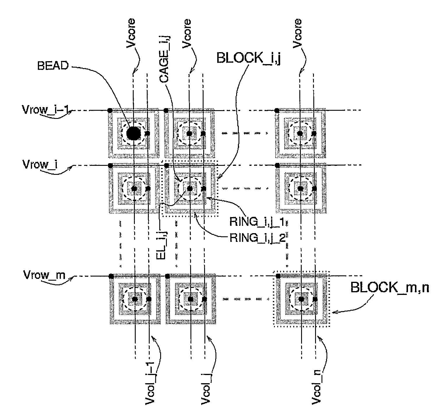
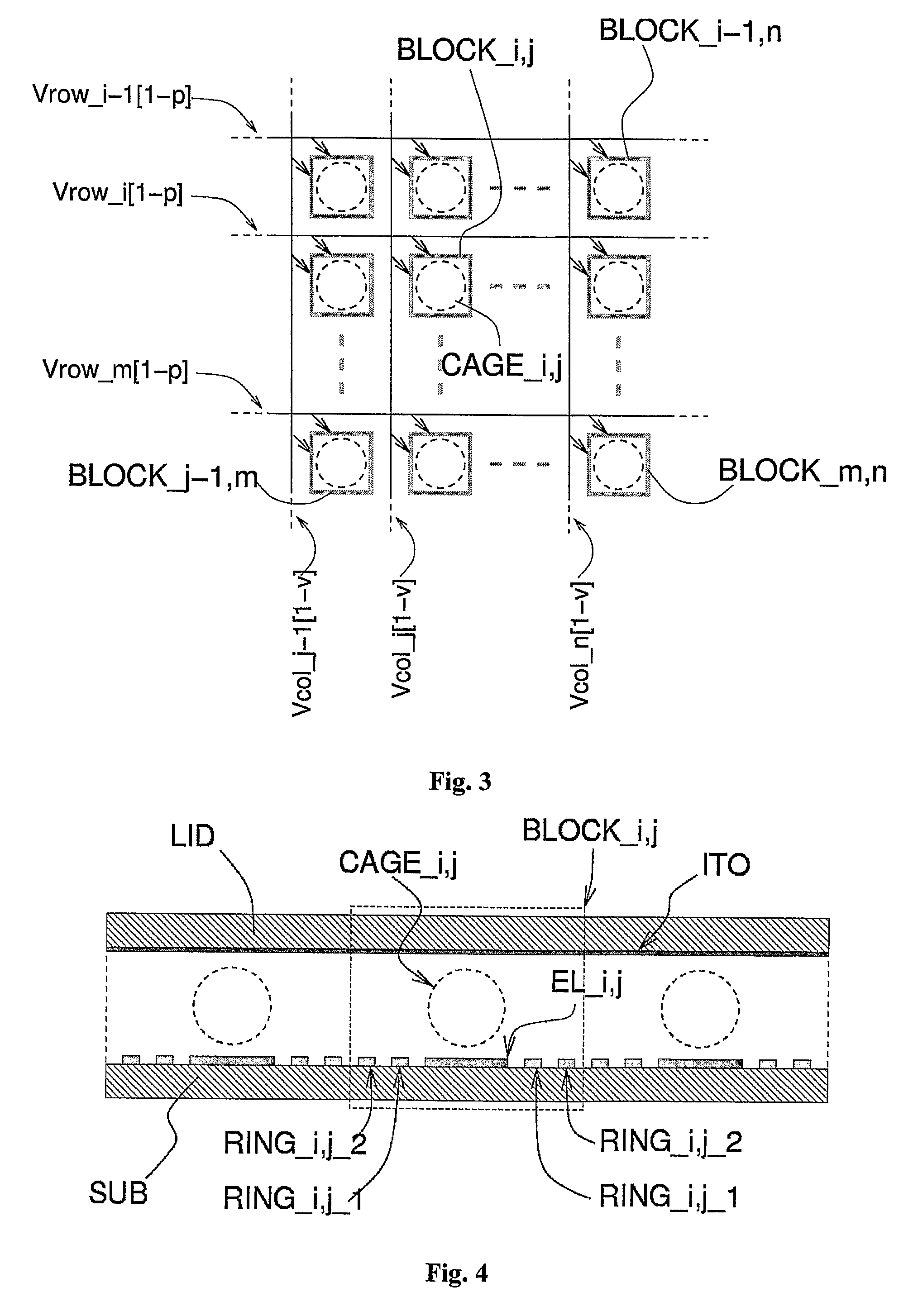
[0093]FIGS. 4 and 5 are, respectively, a cross-sectional view and a top plan view of the apparatus according to the present invention. A homogeneous array of groups (BLOCK_i,j) of electrodes forms an array of size n×m. Each block (BLOCK_i,j) is constituted by a central electrode (EL_i,j) connected to a signal common to the entire array (Vcore) and two concentric electrodes (ring_i,j_1, ring_i,j_2) connected to two different voltages (Vrow_i, Vcol_j) distributed in the array, respectively, in rows and columns as illustrated in FIG. 5. A further signal (Vlid) is connected to the cover (LID), constituted by a single electrode (ITO) (illustrated only in FIG. 4). The device consequently requires as a whole n+m+1+1 signals for control of n×m attraction cages, each of which can entrap a single particle (BEAD) or a group of particles. It is evident that a square array (n=m) minimizes the number of control signals with respect to the number of blocks constituting the n×m array.

[0094]By apply...

second embodiment

[0112]A further embodiment of the method according to the present invention is illustrated schematically in FIG. 20. The method uses a set of points of stable equilibrium that are static for the force (F) that acts on the particles, located within blocks (BLOCK_i,j), the function of which is that of entrapping stably a particle, and a set of points of stable equilibrium moving along lanes in the horizontal direction (HRCH1-HRCHM) or vertical direction (VRCH1-VRCHN). Each of these blocks (BLOCK_i,j) can be configured for entrapping the particle or pushing it within the basin of attraction of one of the points of stable equilibrium moving along the lanes. This can be obtained exploiting one of the methods described according to the present invention, for example joining the point of stable equilibrium of the block to one of the points of stable equilibrium of the lanes. It is evident that each of the particles present in the sample can consequently be parked within the blocks or else ...


PUM

PropertyMeasurementUnit
Timeaaaaaaaaaa
Forceaaaaaaaaaa
Dielectric polarization enthalpyaaaaaaaaaa

Abstract

Method and apparatus for the manipulation and/or control of the position of particles by means of time-variable fields of force. The fields of force can be of dielectrophoresis (positive or negative), electrophoresis, electrohydrodynamic or electrowetting on dielectric, characterized by a set of stable points of equilibrium for the particles.

Description

FIELD OF THE INVENTION[0001]The present invention relates to methods and apparatuses for the manipulation and / or detection of particles. The invention finds application principally in the implementation of biological protocols on individual cells.BACKGROUND OF THE INVENTION[0002]The patent No. PCT / WO 00 / 69565 in the name of G. Medoro describes an apparatus and a method for the manipulation of particles via the use of closed dielectrophoretic-potential cages. The method described teaches how to control the position of each particle independently of all the others in a two-dimensional space. The force used for entrapping the particles in suspension is negative dielectrophoresis. The individual control on the operations of manipulation is carried out by programming memory elements and circuits associated to each element of an array of electrodes integrated in one and the same substrate. There follows an important limitation due to the dimensions of each trap, limited by the need to int...

Claims


Application Information

Patent Timeline
IPC IPC(8): B01D57/02G01N27/26G01R27/26
CPCB03C5/026B03C2201/24G01N27/44756G01N15/1459G01N15/1031G01N27/403B03C5/02
Inventor MEDORO, GIANNIMANARESI, NICOLO
Owner MENARINI SILICON BIOSYSTEMS SPA
Why Eureka
Try Eureka