Inverter controller and high-frequency dielectric heating apparatus

a high-frequency dielectric heating and controller technology, applied in the direction of electric/magnetic/electromagnetic heating, microwave heating, sustainable buildings, etc., to achieve the effect of improving the reliability and usability of the high-frequency dielectric heating apparatus

Active Publication Date: 2009-08-20
PANASONIC CORP
View PDF5 Cites 3 Cited by
  • Summary
  • Abstract
  • Description
  • Claims
  • Application Information

AI Technical Summary

Benefits of technology

[0035]According to the present invention, output is restored to a predetermined value while output control is performed for a predetermined time after release of the power down control in the high-frequency dielectric heating apparatus, so that it is made possible to prevent problem occurrence of the moding phenomenon, overshoot, etc., and improve the reliability and the usability of the high-frequency dielectric heating apparatus.

Problems solved by technology

In the configuration, however, attention is focused on the fact that thermal destruction of the IGBT does not easily occur if the fan fails, and cooking is allowed to continue.

Method used


Image

  • Inverter controller and high-frequency dielectric heating apparatus
  • Inverter controller and high-frequency dielectric heating apparatus
  • Inverter controller and high-frequency dielectric heating apparatus

Examples


Embodiment Construction

[0058]An embodiment of the present invention will be discussed below in detail with the accompanying drawings:

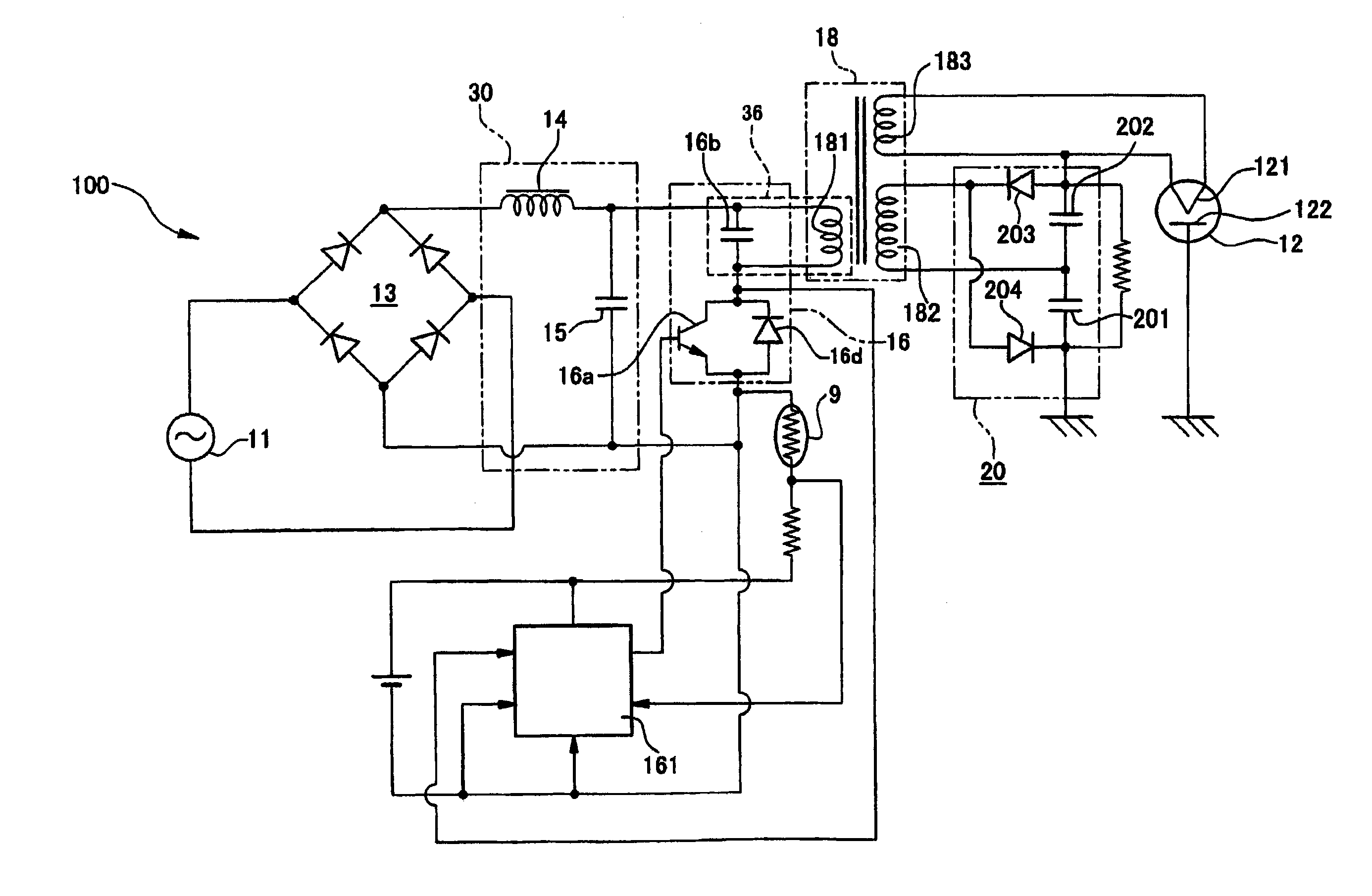
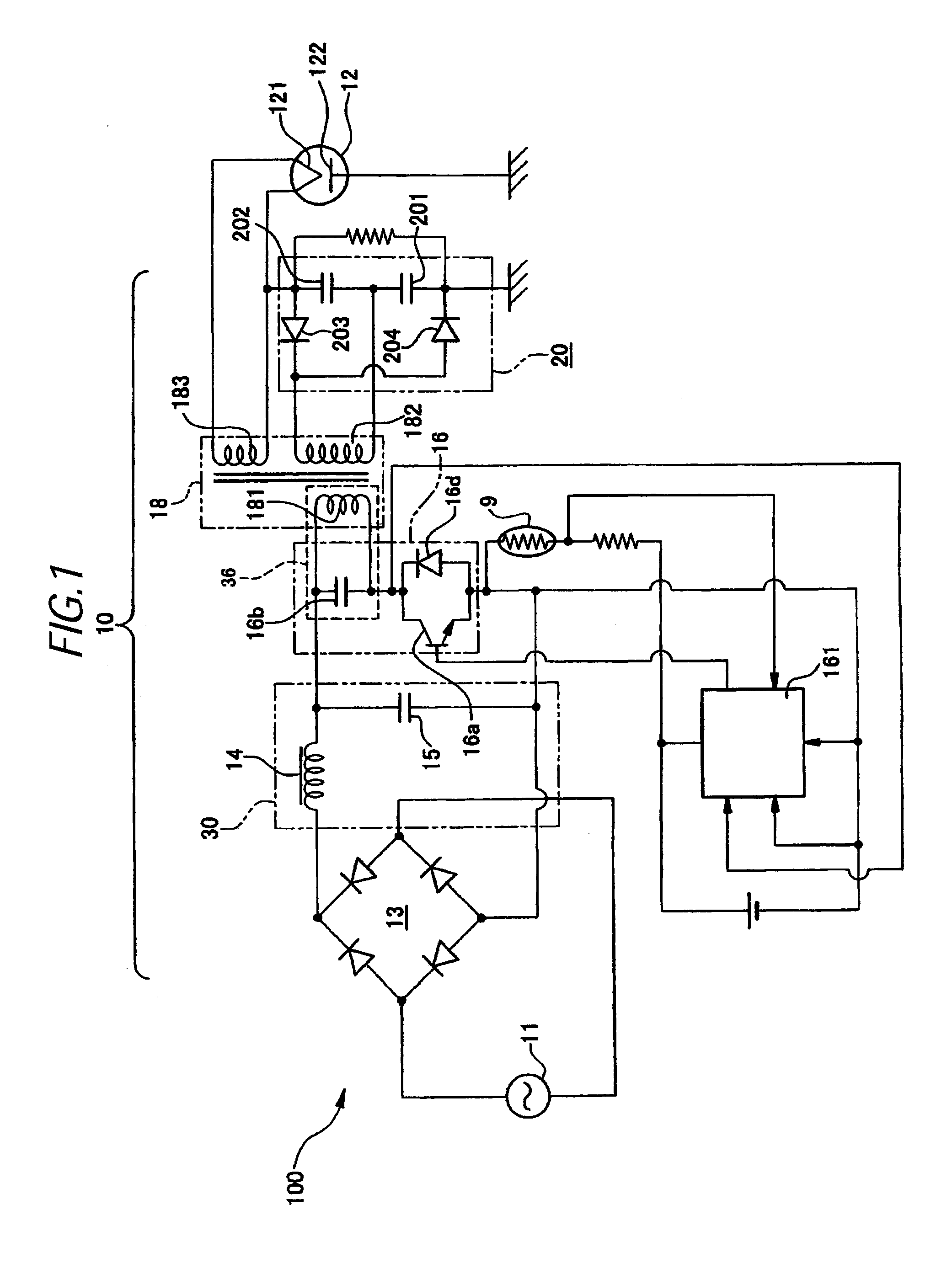
[0059]FIG. 1 is a block diagram of a high-frequency dielectric heating apparatus according to the present invention. A magnetron 12 for generating a microwave generates a microwave and heats an object to be heated such as food stored in a cabinet of a high-frequency dielectric heating apparatus such as a microwave oven. A magnetron drive control circuit 100 includes an inverter main circuit 10 for receiving supply of AC power from an AC power supply 11, a thermistor 9, and an inverter controller 161 for controlling the inverter main circuit 10, and the magnetron drive control circuit 100 performs drive control of the magnetron 12 for generating, stopping, and changing output of a microwave.

[0060]The inverter main circuit 10 supplies the AC power from the AC power supply 11 to the magnetron 12 and includes a rectifier 13 of diode bridge type, a smoothing circuit 30, an invert...


PUM


Abstract

Occurrence of a defect of the moding phenomenon, etc., accompanying rise in output of a magnetron after power down control is prevented and the reliability of a high-voltage dielectric heating apparatus is further improved. After power down control, when the temperature of a thermistor T1 falls again, the resistance value of the thermistor T1 increases and potential Vpc at a point PC also rises and when the potential Vpc becomes higher than Vc3 of another input potential of a comparator C3 (Vpc>Vc3), the comparator C3 outputs “0.” In association with this, a switch S2 is turned off and PD (power down) 2 of a resistor R7 is turned off and thus the input voltage to a positive terminal A and a negative terminal B of a comparator C1 is again restored to 3 V. When the temperature of the thermistor T1 further falls, the resistance value of the thermistor T1 increases and the potential Vpc at the point PC also starts to rise. When the potential Vpc becomes higher than Vc2 of another input potential of a comparator C2, the comparator C2 outputs “0.” Then, a switch S5 turned on in the power down control is turned off through a switch S4 and an OR gate circuit and the partial pressure action of a resistor R11 does not work. The potential at a point SS starts to rise with charge storage in an electrolytic capacitor CO1. When the potential at the point SS continues to rise and exceeds 3 V, a comparator C4 outputs “1,” a NAND gate circuit outputs “0,” and a moving contact K1 is switched to the side of a second fixed terminal b. The input voltage to the positive terminal A, the negative terminal B of the comparator C1 starts to rise.

Description

TECHNICAL FIELD[0001]This invention relates to high-frequency dielectric heating using a magnetron like a microwave oven and, in particular, to overheat protection for semiconductor switching elements used in an inverter and prevention of overvoltage applied to the magnetron.BACKGROUND ART[0002]Hitherto, in a high-frequency dielectric heating apparatus using a magnetron such as a microwave oven, electric power supplied to the magnetron has been adjusted based on the pulse width of output signal from an inverter controller. To increase the output power, the pulse width of the output signal form the inverter controller has been widened, thereby increasing the electric power supplied to the magnetron. This configuration makes it possible to continuously change heat output of the magnetron.[0003]FIG. 6 is a block diagram including a magnetron used in a high-frequency dielectric heating apparatus in a prior art. In FIG. 6, alternating current from a commercial power supply 11 is rectifie...

Claims


Application Information

Patent Timeline
Patent Type & Authority Applications(United States)
IPC IPC(8): H05B6/66
CPCH02M1/32H05B6/666H02M7/537H02H7/1213H05B6/683Y02B40/00
Inventor KINOSHITA, MANABUSUENAGA, HARUOYASUI, KENJISAKAI, SHINICHISHIROKAWA, NOBUOMORIYA, HIDEAKI
Owner PANASONIC CORP
Why Eureka
Try Eureka