Fluid recycling apparatus and fuel cell system having the fluid recycling apparatus

a technology of fluid recycling and fluid recycling, which is applied in the direction of machines/engines, electrochemical generators, positive displacement liquid engines, etc., can solve the problems of reducing the power efficiency of the typical fuel cell system, separating from the unreacted oxidizing gas, and low orientation free performan

Inactive Publication Date: 2009-08-20
SAMSUNG SDI CO LTD +1
View PDF5 Cites 5 Cited by
  • Summary
  • Abstract
  • Description
  • Claims
  • Application Information

AI Technical Summary

Benefits of technology

[0011]Exemplary embodiments of the present disclosure provide a fluid recycling apparatus that can separate liquid and gas th

Problems solved by technology

As a result, the water separated from the unreacted oxidizing gas may be remixed with the unreacted oxidizing gas or leaked from the fuel cell system.
This problem is generally expressed as

Method used


Image

  • Fluid recycling apparatus and fuel cell system having the fluid recycling apparatus
  • Fluid recycling apparatus and fuel cell system having the fluid recycling apparatus
  • Fluid recycling apparatus and fuel cell system having the fluid recycling apparatus

Examples


Embodiment Construction

[0044]Certain embodiments will be described more fully hereinafter with reference to the accompanying drawings, in which exemplary embodiments are shown. As those skilled in the art would realize, the described embodiments may be modified in various different ways, all without departing from the spirit or scope of the present disclosure.

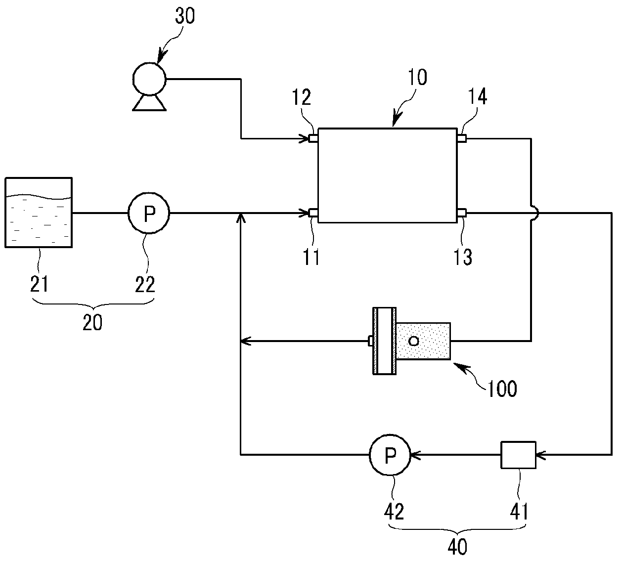
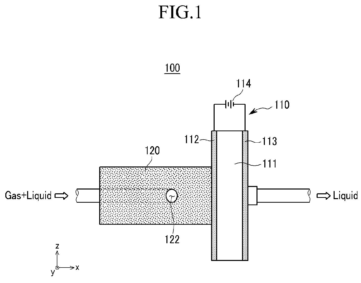
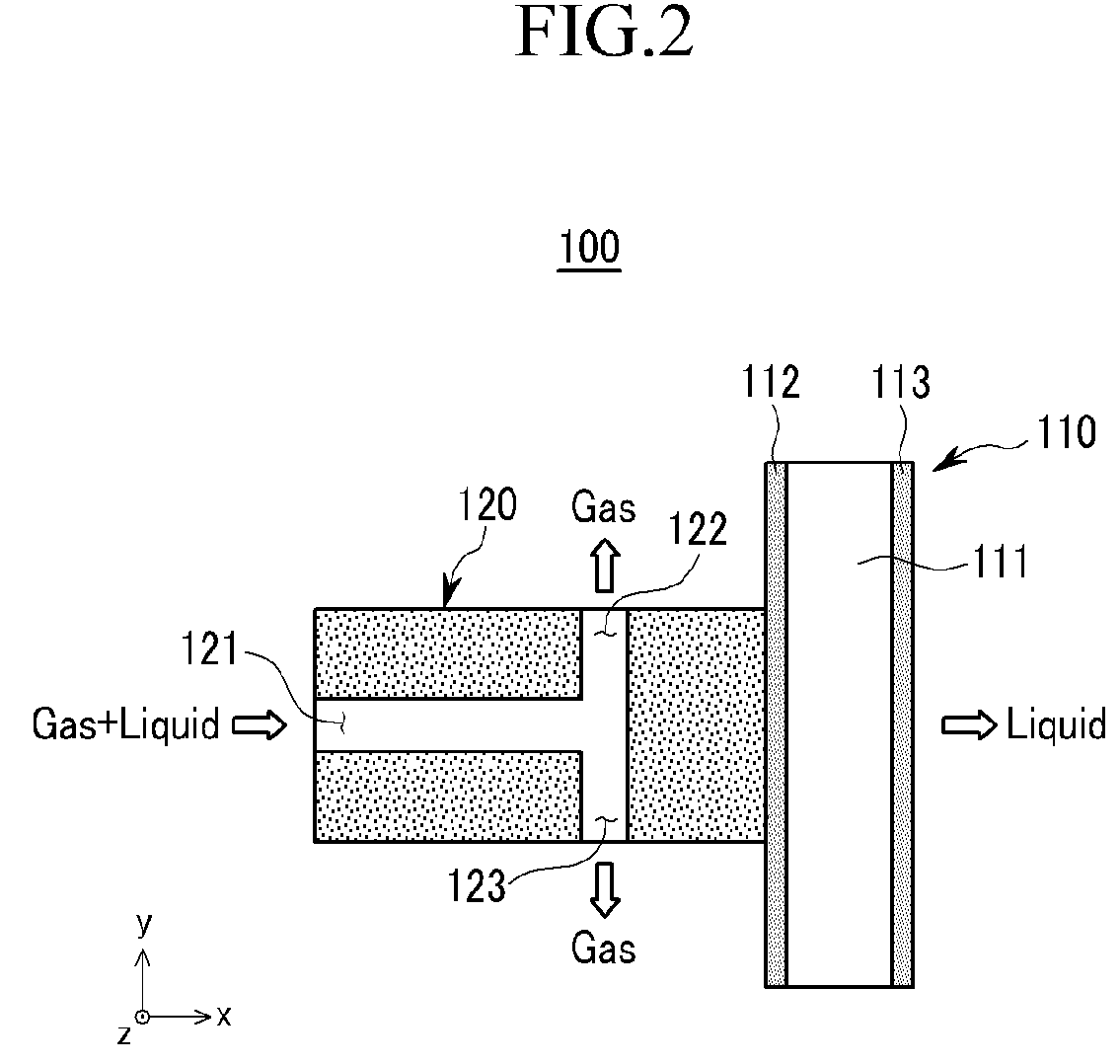
[0045]FIG. 1 is a schematic diagram of a fluid recycling apparatus 100 according to a first exemplary embodiment of the present disclosure, and FIG. 2 is a cross-sectional view of the fluid recycling apparatus of FIG. 1, taken in a fluid flow direction.

[0046]As shown in FIGS. 1 and 2, a fluid recycling apparatus 100 in accordance with a first exemplary embodiment of the present disclosure includes an electric penetration or electroosmotic pump 110 and a gas / liquid separation unit 120. The fluid recycling apparatus 100 separates moisture from a fluid. For example, the fuel cell system uses air from the atmosphere as an oxidizing gas. Moisture generate...


PUM


Abstract

An improved fluid recycling apparatus and a fuel cell system comprising the same effectively recycle moisture contained in fluid circulating in a fuel cell system and operate independent of orientation. The fluid recycling apparatus includes an electric penetration pump and a gas/liquid separation unit. The electric penetration pump has first and second electrodes and an electric penetration layer interposed between the first and second electrodes. The electric penetration pump directs a liquefied fluid through an electric fluid passage formed in the electric penetration layer by applying a voltage between the first electrode and the second electrode. The gas/liquid separation unit is disposed upstream of the electric fluid passage, contacting the electric penetration pump, and comprises a porous material that can absorb the liquefied fluid. The gas/liquid separation unit comprises at least one fluid inflow hole through which a mixture of a gaseous fluid and a liquefied fluid is introduced, and at least one gas discharge hole communicating with the fluid inflow hole configured for discharging the gaseous fluid.

Description

CROSS-REFERENCE TO RELATED APPLICATION[0001]This application claims priority to and the benefit of Korean Patent Application No. 10-2008-0015007, filed in the Korean Intellectual Property Office on Feb. 19, 2008, the entire contents of which is incorporated herein by reference.BACKGROUND[0002]1. Technical Field[0003]The present disclosure relates to a fuel cell system and, more particularly, to a fluid recycling apparatus effectively recycles water from fluid circulating in the fuel cell system and operates independent of orientation.[0004]2. Description of the Related Art[0005]Fuel cell systems generate electrical energy through an electrochemical reaction between hydrogen and oxygen. Fuel cells are classified into a variety of types according to fuel used such as polymer electrolyte membrane fuel cells (PEMFCs), direct methanol fuel cells (DMFCs), and the like.[0006]PEMFCs use a hydrogen ion exchange polymer membrane as an electrolyte membrane. A fuel containing hydrogen electroch...

Claims


Application Information

Patent Timeline
IPC IPC(8): H01M8/06F04F99/00
CPCH01M8/04007H01M8/04097H01M8/04164Y02E60/50H01M8/1011H01M2008/1095H01M8/04171H01M8/04
Inventor PARK, JUNG-KURNYOON, SEONG-KEECHO, HYE-JUNGYANAGISAWA, ICHIROFURUKAWA, HIDEKIFUJII, MITSUTAKA
Owner SAMSUNG SDI CO LTD
Why Eureka
Try Eureka