Pulse-wave measurement apparatus

a measurement apparatus and pulse wave technology, applied in the field of pulse wave measurement apparatus, can solve the problems of difficult positioning and placing a single sensor device just above the flat portion formed in the artery, and achieve the effect of reducing the error of pulse wave detection and preventing the nonlinearity of output characteristics

Inactive Publication Date: 2009-08-20
OMRON HEALTHCARE CO LTD
View PDF1 Cites 4 Cited by
  • Summary
  • Abstract
  • Description
  • Claims
  • Application Information

AI Technical Summary

Benefits of technology

[0023]According to the present invention, it is possible to prevent the nonlinearity of the output characteristic, thereby reducing the error of the pulse-wave detection.

Problems solved by technology

In consideration of the aforementioned circumstances, it is significantly hard to position and place a single sensor device just above the flat portion formed in the artery.

Method used


Image

  • Pulse-wave measurement apparatus
  • Pulse-wave measurement apparatus
  • Pulse-wave measurement apparatus

Examples


first embodiment

[0040][The Structure and Basic Operations of Pulse-Wave Measurement Apparatus]

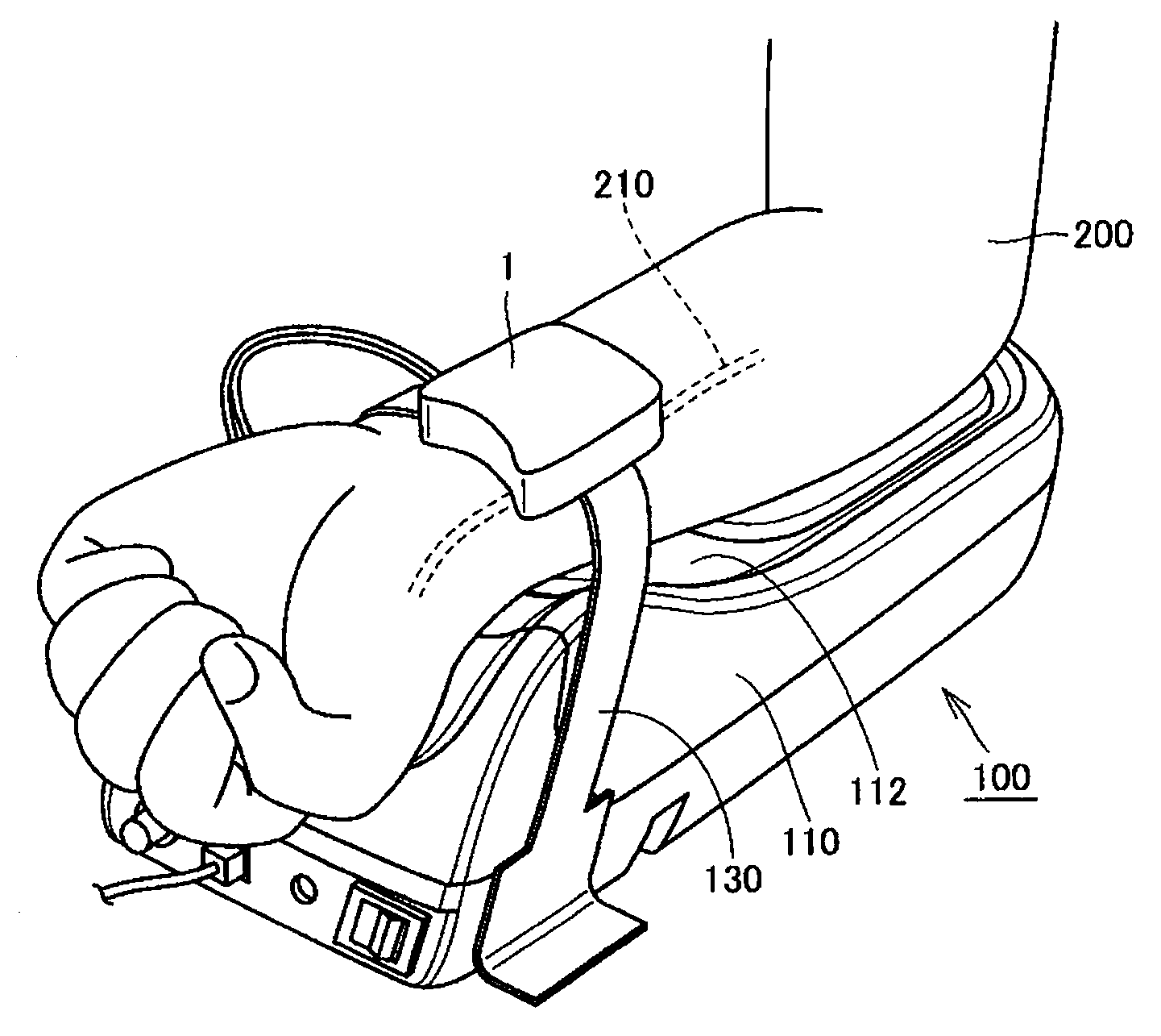
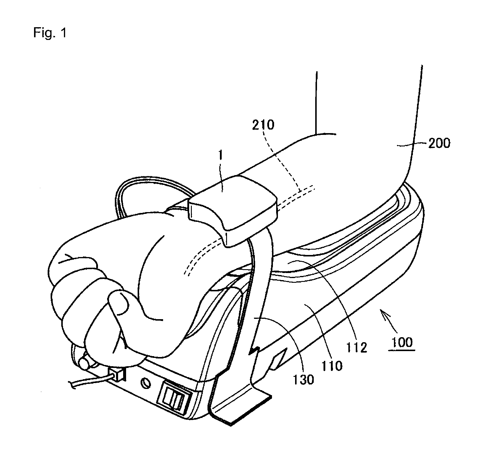
[0041]FIG. 1 is an external view of a pulse-wave measurement apparatus according to the first embodiment of the present invention. Further, FIG. 1 illustrates a measurement state where a sensor array is pressed against a carpus. FIG. 2 is a schematic cross-sectional view of the carpus and the pulse-wave measurement apparatus at the measurement state illustrated in FIG. 1.

[0042]Referring to FIGS. 1 and 2, the pulse-wave measurement apparatus 100 is for measuring pressure waveforms in an artery in a carpus of a to-be-tested person. The pulse-wave measurement apparatus 100 includes a placement table 110, a sensor unit 1 and a fastening belt 130. The sensor unit 1 includes a casing 122, a pressing cuff 18 and a sensor array 19.

[0043]The placement table 110 includes a placement portion 112 for placing the carpus and the forearm of one arm 200 of the to-be-tested person. The fastening belt 130 secures the carpus...

second embodiment

[0113]The present embodiment relates to a pulse-wave measurement apparatus having a C-V conversion portion 21 with a changed structure.

[0114][The Structure of the C-V Conversion Portion]

[0115]FIG. 11 is a circuit diagram illustrating the structures of the C-V conversion portion 21 and a capacitor CX in the pulse-wave measurement apparatus according to the second embodiment of the present invention.

[0116]Referring to FIG. 11, the voltage setting portion 54 according to the second embodiment of the present invention includes a capacitor (a voltage setting capacitor) CS, instead of the switch SW4.

[0117]The capacitor CS is connected at its one end to the other end of the switch SW1 and one end of the switch SW2 and, also, is connected at the other end to a predetermined voltage, such as a negative voltage of VEE.

[0118][Operations of the C-V Conversion Portion]

[0119]FIG. 12 is a timing chart illustrating the operations of the C-V conversion portion 21 when the pulse-wave measurement appa...


PUM


Abstract

A pulse-wave measurement apparatus includes a pressure detecting capacitor which changes its capacitance according to the pressure within an artery; an operational amplifier which is connected at its inverting input terminal to one end of the pressure detecting capacitor and also is connected at its non-inverting input terminal to a reference voltage; a charge transfer capacitor; a switch which is connected to the inverting input terminal of the operational amplifier; and a voltage setting portion which is connected to the switch and to the output of the operational amplifier. The voltage setting portion is adapted to connect the other end of the switch to the output of the operational amplifier or to disconnect the other end of the switch from the output of the operational amplifier and applies a predetermined voltage to the other end of the switch.

Description

REFERENCE TO RELATED APPLICATIONS[0001]This application is a national stage application under 35 USC 371 of International Application No. PCT / JP2007 / 057380, filed Apr. 2, 2007, which claims the priority of Japanese Patent Application No. 2006-122206, filed Apr. 26, 2006, the contents of both of which prior applications are incorporated herein by reference.FIELD OF THE INVENTION[0002]The present invention relates to a pulse-wave measurement apparatus and, more particularly, relates to a pulse-wave measurement apparatus for measuring pressure waveforms in an artery using a capacitance device.BACKGROUND OF THE INVENTION[0003]As a pressure-pulse-wave measurement method for easily obtaining pressure waveforms in an artery in a bloodless manner, there has been known a tonometry method described in G. L. Pressman, P. M. Newgard, “A Transducer for the Continuous External Measurement of Arterial Blood Pressure”, IEEE TRANSACTIONS ON BIO-MEDICAL ELECTRONICS, 1963, pp. 74-81. In the tonometry ...

Claims


Application Information

Patent Timeline
Patent Type & Authority Applications(United States)
IPC IPC(8): A61B5/02
CPCA61B5/021A61B5/02125G01R27/2605G01L1/144G01L1/146G01D5/24
Inventor TANABE, KAZUHISA
Owner OMRON HEALTHCARE CO LTD
Why Eureka
Try Eureka