
Pressure control valve

a technology of pressure control valve and relief valve, which is applied in the direction of fluid pressure control, valve type, instrument, etc., can solve the problems that the pressure supplied from an outside pressure set pressure of the relief valve against the pilot signal cannot be accurately controlled, and the inconvenience of the operator, so as to reduce manufacturing costs, prevent the falling of a working device, and accurately control the

Active Publication Date: 2009-08-27
VOLVO CONSTR EQUIP
View PDF2 Cites 13 Cited by
  • Summary
  • Abstract
  • Description
  • Claims
  • Application Information

AI Technical Summary

Benefits of technology

[0025]An embodiment of the present invention relates to a pressure control valve, in which, in the case of jointly connecting a pipe for supplying pilot signal pressure from an outside to a pilot port, the connection work can be done without being interfered by components around a relief valve.
[0027]An embodiment of the present invention relates to a pressure control valve, which can reduce the manufacturing cost since the use of a sealing part (e.g. O-ring) for sealing a gap between contact surfaces of a piston is not required, and can solve the problem that the set pressure of a relief valve against the pilot pressure cannot be accurately controlled due to the frictional resistance caused by sealing mounting.
[0028]An embodiment of the present invention relates to a pressure control valve, which can prevent the hydraulic fluid fed from the hydraulic pump and waiting in the pressure chamber from leaking to the hydraulic tank side, and thus can prevent the falling of a working device when load is generated on an inlet port side of a relief valve.
[0029]An embodiment of the present invention relates to a pressure control valve, which can keep the reduction of an elastic force of a pilot poppet spring within a preset range, and thus can control the minimum pressure of a hydraulic pump against the pilot signal pressure to be constant.
[0032]The pressure control valve according to a preferred embodiment of the present invention may further include a first stopper slidably installed in the guide to face the pilot poppet and to prevent the set pressure of the pilot poppet spring from being lowered below a predetermined value.
[0035]The pressure control valve according to a preferred embodiment of the present invention may further include a sealing part mounted on an outer side of the poppet to seal a gap between mutual contact surfaces of the sleeve and the poppet, so that the hydraulic fluid in the pressure chamber is prevented from leaking to the hydraulic tank through the gap.

Problems solved by technology

In the case of controlling the set pressure of the relief valve, it is required for an operator to set the pressure of the relief valve as an operator directly confirms a pressure gauge, and this causes the operator inconvenience.
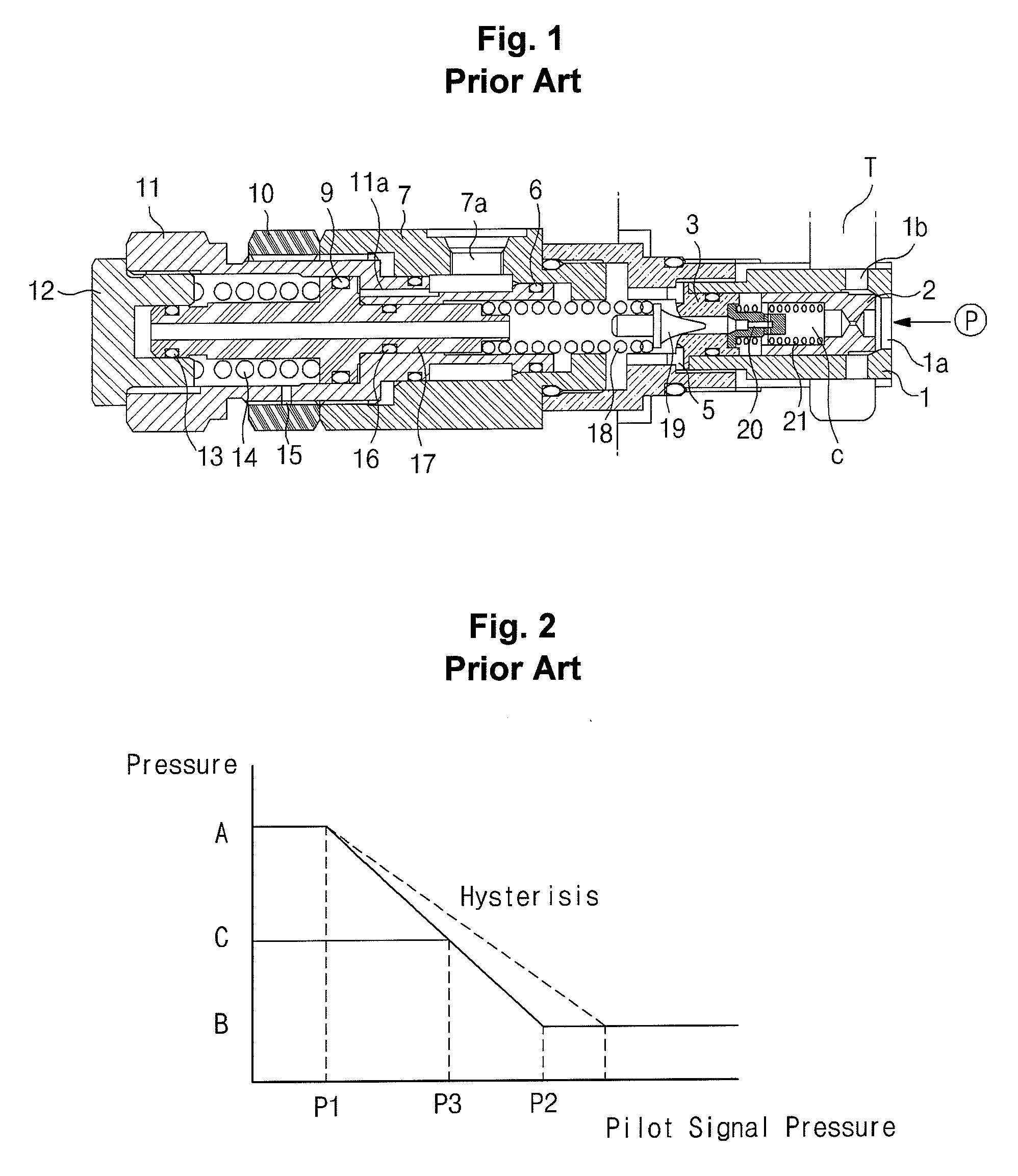
Accordingly, as illustrated in FIG. 2, a hysteresis occurs, whereby the set pressure of the relief valve against the pilot signal pressure supplied from an outside cannot be accurately controlled.
At this time, if load is generated on the inlet port side 1a of the first plug 1, a safety accident, such as falling of a working device (e.g. boom or the like), may occur.
In addition, in the case of setting the minimum pressure of the relief valve, the range of the minimum pressure is enlarged due to tolerance of components constituting the relief valve, and thus it becomes impossible to form the pressure desired by the user (e.g., in the case where the minimum pressure of the relief valve is 100 kg / cm2, the actual pressure may be set to 110 kg / cm2.

Method used


Image

  • Pressure control valve
  • Pressure control valve
  • Pressure control valve

Examples


Embodiment Construction

[0043]Hereinafter, preferred embodiments of the present invention will be described with reference to the accompanying drawings. The matters defined in the description, such as the detailed construction and elements, are nothing but specific details provided to assist those of ordinary skill in the art in a comprehensive understanding of the invention, and thus the present invention is not limited thereto.

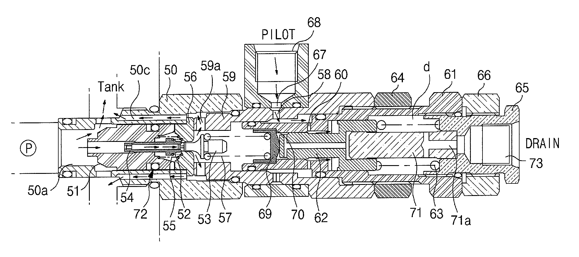
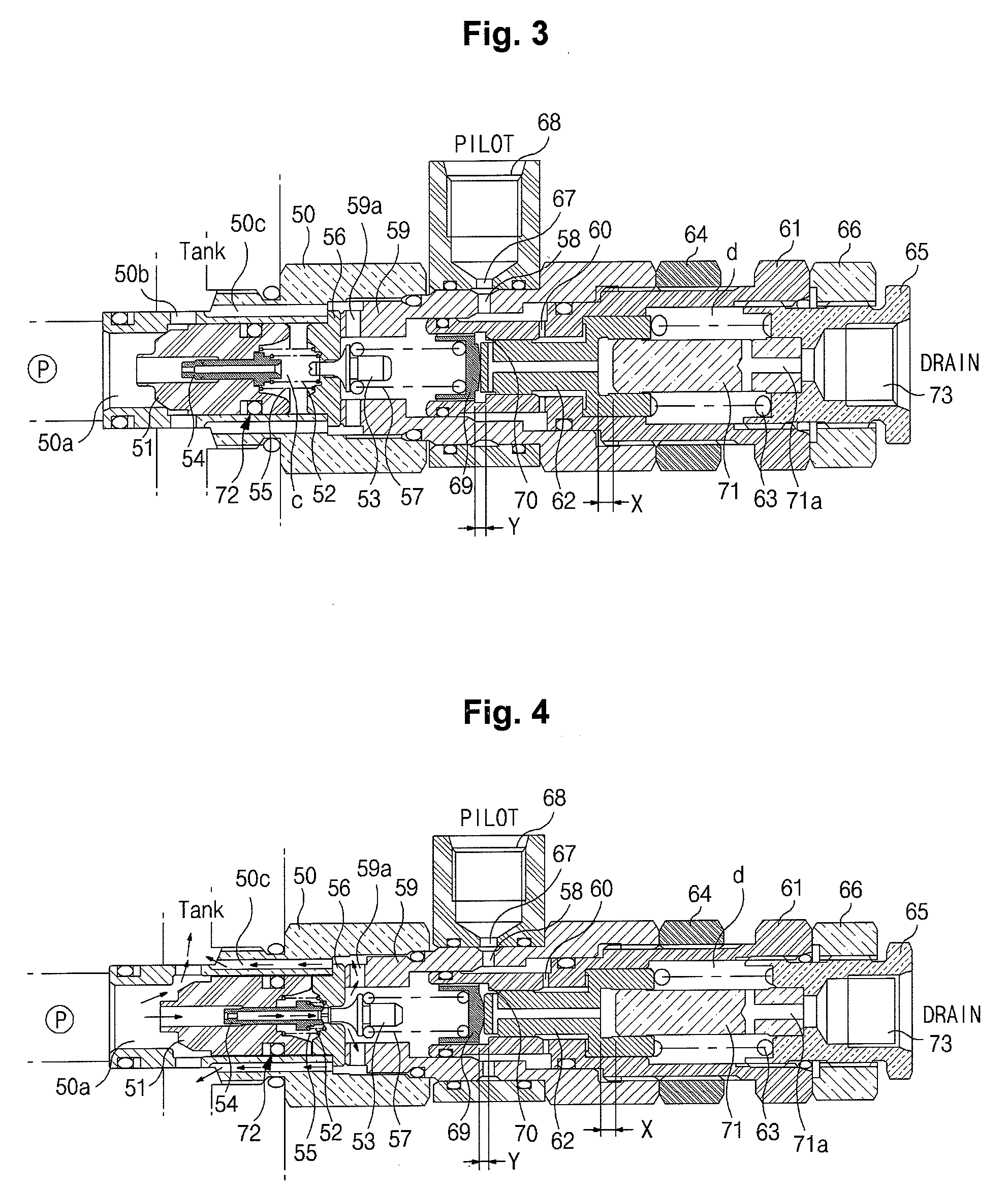
[0044]As shown in FIGS. 3 to 5, a pressure control valve according to an embodiment of the present invention includes a sleeve 50 having an inlet port 50a into which high-pressure hydraulic fluid from a hydraulic pump P flows, and a tank path 50b communicating with a hydraulic tank T; a poppet 51 slidably coupled within the sleeve 50 to open / close a flow path between the inlet port 50a and the tank path 50b; a piston 54 elastically supported by a spring 52 to slidably move within the poppet 51, and becoming in contact with the pilot poppet 53 when it moves by an initial pressure of...


PUM


Abstract

A pressure control valve is provided, which can variably control the set pressure of a relief valve in accordance with pilot signal pressure that is controlled in an operator's seat and so on when the set pressure of the relief valve required in a replaced working device is changed. The pressure control valve includes a sleeve having an inlet port and a tank path, a poppet opening / closing a flow path between the inlet port and the tank path, a poppet spring elastically supporting the path between the inlet port and the tank path in a closed state, a valve sheet installed to face the poppet so that a set pressure is formed in a pressure chamber of the sleeve, a pilot poppet draining the hydraulic fluid in the pressure chamber to the hydraulic tank when high pressure that exceeds the set pressure is generated in the pressure chamber, a pilot poppet spring elastically supporting the path of the valve sheet in a closed state, a plug coupled to the sleeve and having a pilot port to receive the pilot signal pressure from an outside, a main piston slidably coupled within a guide coupled to the plug to variably control the set pressure in the pressure chamber in accordance with the pilot signal pressure, and a control plug movably coupled to the guide to control a set pressure of a spring supporting the main piston.

Description

CROSS-REFERENCE TO RELATED APPLICATION[0001]This application is based on and claims priority from Korean Patent Application No. 10-2008-0016910, filed on Feb. 25, 2008 in the Korean Intellectual Property Office, the disclosure of which is incorporated herein in its entirety by reference.BACKGROUND OF THE INVENTION[0002]1. Field of the Invention[0003]The present invention relates to a pressure control valve that can variably control a set pressure of a relief valve by pilot signal pressure supplied from an outside.[0004]More particularly, the present invention relates to a pressure control valve that can variably control the set pressure of a relief valve in accordance with pilot signal pressure controlled in an operator's seat and so on when the set pressure of the relief valve required in a working device (e.g. an option device) is changed.[0005]2. Description of the Prior Art[0006]In general, a pressure control valve is used within a set pressure of a hydraulic circuit. In the cas...

Claims


Application Information

Patent Timeline
Patent Type & Authority Applications(United States)
IPC IPC(8): F16K31/12
CPCG05D16/18F16K17/105G05D16/101G05D16/109G05D16/187Y10T137/7762Y10T137/777Y10T137/7766F15B11/02F16K17/00
Inventor JEON, MAN SUK
Owner VOLVO CONSTR EQUIP
Learn More