Heat Reservoir for a Steam Engine

a technology for steam engines and heat reservoirs, which is applied in the field of heat reservoirs for steam engines, can solve the problems of inconvenient refueling, low heat exchange rate, and high cost of fuel, and achieve the effect of maximizing the efficiency of the heat exchanger tube and maximizing the heat exchange ra

Inactive Publication Date: 2009-08-27
KODAK JAMES ALLEN
View PDF7 Cites 1 Cited by
  • Summary
  • Abstract
  • Description
  • Claims
  • Application Information

AI Technical Summary

Benefits of technology

[0006]The present invention is a heat reservoir that can serve as a boiler in a steam engine. It converts electrical energy into heat which is then used to make steam that drives a piston or turbine engine. Electrical energy is applied to a heating coil which is in contact with a reservoir containing aluminum, alumina or magnesium. The coil heats the aluminum at least to a temperature sufficient to convert water to steam. To prevent loss of heat, the aluminum is surrounded by a container with an extremely low thermal conductance. Water is pumped through a heat exchanger innervating the reservoir so that the water is converted to steam. This steam is then used to drive a piston or turbine engine. The residual steam then flows into a condenser which returns the steam to its liquid form.
[0008]Finally, in order to maximize the efficiency of the heat exchanger tube innervating the heat reservoir, the heat exchanger is equipped with corrugated appendages emanating from the outer skin of the heat exchanger tube and into the heat storage media in order to maximize the rate of heat exchange between the two.

Problems solved by technology

The internal combustion engine powering the vast majority of today's automobiles, power boats and lawn mowers has many drawbacks: the cost of fuel, the inconvenience of refueling, the depletion of a finite energy source, and the environmental impact of extracting, transporting, and burning billions of barrels of petroleum every year.
Utilizing electrical energy is one alternative, but this approach has required the use of batteries that have to date been proven to be too heavy, too expensive, and too limited in capacity to be of significant marketable use.
Without the boiler, there is no longer the need to vent combusted gas products and thus the greatest source of inefficiency in automotive steam engines is ablated.
The use of heat as a significant means of energy storage has received far less attention and efforts in this regard have been generally limited to home heating or providing a means for power stations to store energy during non-peak hours.
The exceedingly high volume required to store any significant amount of heat in this way makes this technology ill-suited for any common purpose.
Since an automobile has very limited area available for solar panels, the amount of energy so derived is merely supplemental and can only marginally extend the range of an electric vehicle.

Method used


Image

  • Heat Reservoir for a Steam Engine
  • Heat Reservoir for a Steam Engine
  • Heat Reservoir for a Steam Engine

Examples


Embodiment Construction

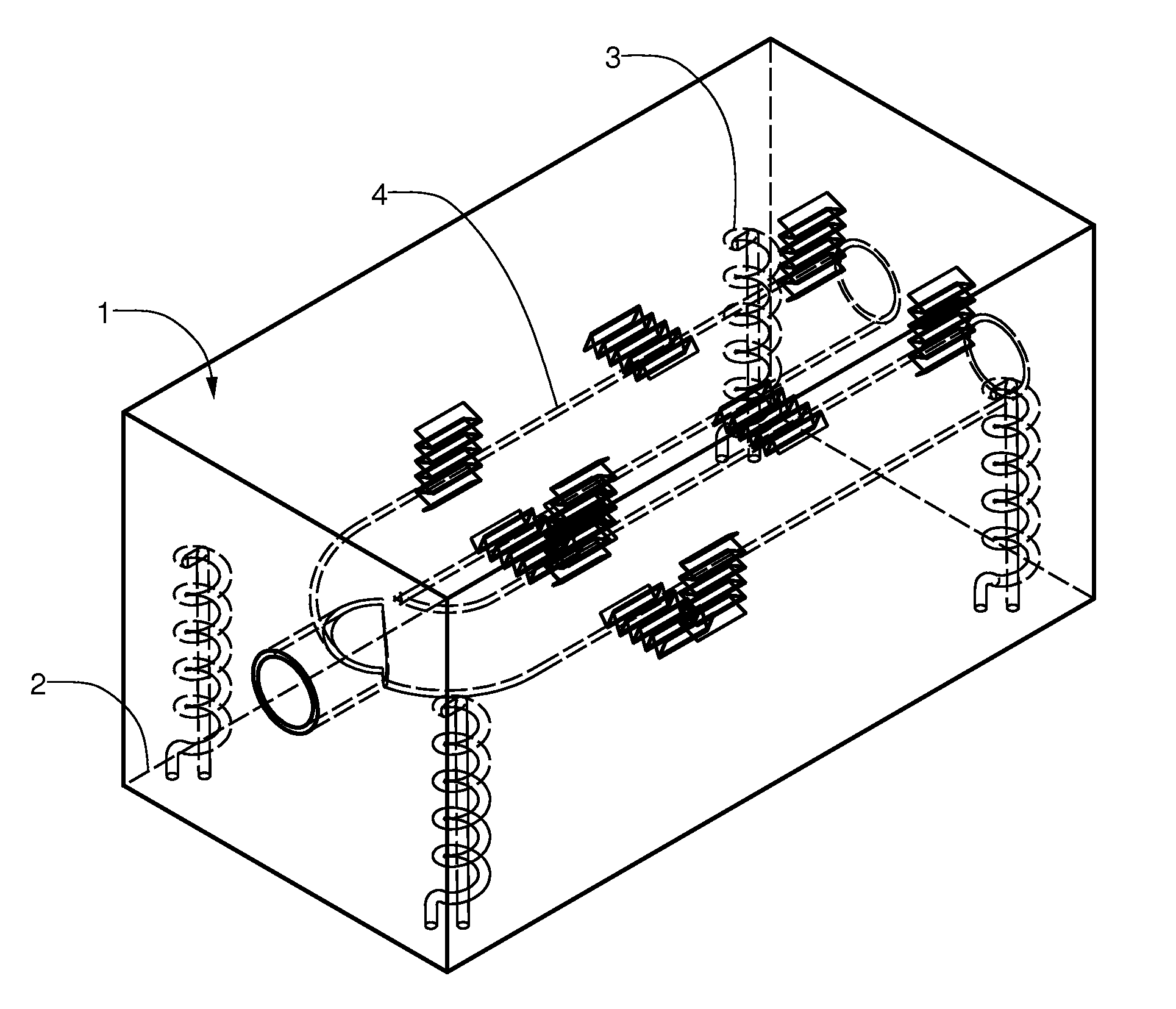
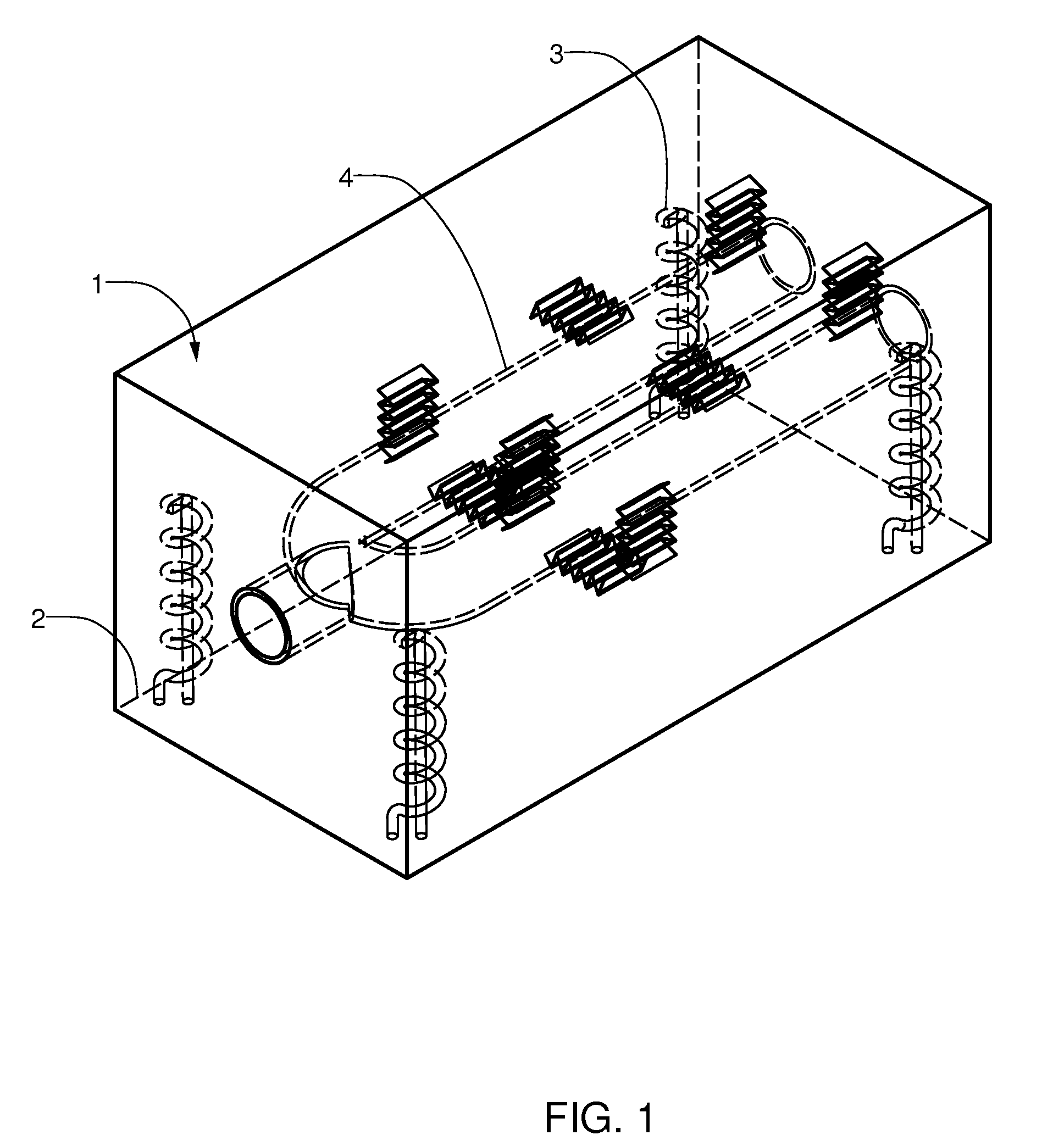
[0014]The preferred embodiment is a reservoir as shown in FIG. 1. The reservoir contains a heat storage material 1 comprised of mostly aluminum. The reservoir is generally cubical and the aluminum is enclosed within an insulating jacket 2. The heat storage material is heated using electrical resistance coils 3 and the heat stored within the reservoir is retrieved using a heat exchanger 4 through which a working fluid, such as water, can flow.

[0015]The maximum amount of heat energy that can be stored by the reservoir is a function of the amount of aluminum contained within the reservoir and the temperature to which it is heated. Between the temperatures of 150° C. and 657° C., aluminum has an average heat capacity of 1.1 J / g-° C. At 657° C., aluminum melts and exhibits a relatively high heat of fusion, 400 J / g. Thereafter, in the liquid phase, aluminum exhibits a constant heat capacity of 1.2 J / g-° C. Therefore, between the preferred operating temperatures of 150° C. to 800° C., 500 ...


PUM


Abstract

A heat reservoir for storing the energy necessary for powering heat engines, particularly steam engines, is disclosed. The heat reservoir converts electrical energy into thermal energy through the use of electrical resistance heating coils bathed in one or more high heat capacity metals. Loss of heat through thermal conduction is minimized through the use of an insulating jacket surrounding the reservoir. The stored heat can be quickly transferred to a working fluid, such as steam, by using both a heat storage metal and a heat exchanger metal that possess high thermal conductivity.

Description

BACKGROUND OF THE INVENTION[0001]The internal combustion engine powering the vast majority of today's automobiles, power boats and lawn mowers has many drawbacks: the cost of fuel, the inconvenience of refueling, the depletion of a finite energy source, and the environmental impact of extracting, transporting, and burning billions of barrels of petroleum every year. There has thus been a long standing effort to develop alternative automotive energy sources. Utilizing electrical energy is one alternative, but this approach has required the use of batteries that have to date been proven to be too heavy, too expensive, and too limited in capacity to be of significant marketable use. The enclosed invention depends on electricity as the ultimate source of energy but stores that energy in a more practical way. Rather than relying on batteries, the electrical energy is converted to and stored as heat within a reservoir. This heat reservoir serves essentially as a replacement for the boiler...

Claims


Application Information

Patent Timeline
Patent Type & Authority Applications(United States)
IPC IPC(8): F24J3/00
CPCB60K3/00F01K3/00F01K15/02Y02E60/142F22B1/28F28D20/0056F28F27/02F22B1/028Y02E60/14
Inventor KODAK, JAMES ALLEN
Owner KODAK JAMES ALLEN
Why Eureka
Try Eureka