Cooling Plate Assembly with Fixed and Articulated Interfaces, and Method for Producing Same

a technology of cooling plate and interface, which is applied in the direction of manufacturing tools, electrical apparatus construction details, and semiconductor/solid-state device details, etc., can solve the problems of reducing the functional performance, reliability and life expectancy of electronic components, and not providing a low enough thermal resistance path. , to achieve the effect of improving the functional performance and reliability of electronic components, and reducing the cost of production

Inactive Publication Date: 2009-08-27
IBM CORP
View PDF9 Cites 65 Cited by
  • Summary
  • Abstract
  • Description
  • Claims
  • Application Information

AI Technical Summary

Benefits of technology

[0014]According to the preferred embodiments of the present invention, a cooling plate assembly for transferring heat from electronic components mounted on a circuit board includes both fixed and articulated interfaces. A fixed-gap coldplate is positioned over and in thermal contact with (e.g., through an elastomerically compressive pad thermal interface material) electronic components mounted on the circuit board's top surface. An articulated coldplate is positioned over and in thermal contact with at least one electronic component mounted on the circuit board's top surface. In the preferred embodiments, the articulated coldplate is spring-loaded against one or more high power processor components having power dissipation greater than that of the electronic components under the fixed-gap cooling plate. Thermal dissipation channels in the coldplates are interconnected by flexible tubing, such as copper tubing with a free-expansion loop. In the preferred embodiments, the coldplates and the flexible tubing are connected to define a portion of a single flow loop used to circulate cooling fluid through the coldplates.

Problems solved by technology

Excessive temperature degrades electronic component functional performance, reliability, and life expectancy.
With this much higher heat load, the traditional method of sinking heat through the electronic component interconnect and through the circuit board copper planes, as well as through the backside coldplate, does not provide a low enough thermal resistance path.
Accordingly, this much higher heat load will result in a processor junction temperature that exceeds acceptable temperature limits for system functionality and reliability.
Removing heat from the component topside, either by conduction through a thermally conductive cooling plate to the computer chassis structure or via fluid convection through an attached liquid-cooled cooling plate, results in a much lower thermal resistance path to the external environment.
Unfortunately, the utilization of a thick layer of compressive pad TIM in the requisite large gap will not enable a high performance interface needed for the high power processors now desired for military applications.
However, screening parts for package height is undesirable due to the loss in yield of relatively expensive parts
Both of these options drive higher cost in manufacturing due to the need for customization of each processor circuit board over the life of the product build cycle.
In addition, the need for customization makes maintenance in the field difficult because neither the critical components nor the coldplate can be replaced with standard parts.
However, it is difficult to apply this single articulated-gap coldplate option to applications where numerous components are to be cooled and / or the components to be cooled are spread over a large region of the processor circuit board.
Moreover, the larger the region of the processor circuit board populated by the components to be cooled, the larger the mass of the articulated-gap cooling plate.
An articulated-gap cooling plate having a large mass is undesirable in military and other applications that require operation in high g-force environments (e.g., fighter aircraft, space vehicles, and the like) because high g-forces may cause the cooling plate to momentarily pull away from the components to be cooled (reducing the performance of the interface by introduction of air gap from voids or delamination) and then be forced back into contact with those components (possibly damaging the components).
While this option allows for mechanically independent attach solutions for each coldplate / component (or module) combination and allows each coldplate to have a relatively small mass, it greatly increases the risk of leaking, given the large number of flexible tube interconnects.
Such an increase in the risk of coolant leaking from the tubing increases the risk of component failure, and increases the risk of fire if the coolant is flammable.

Method used


Image

  • Cooling Plate Assembly with Fixed and Articulated Interfaces, and Method for Producing Same
  • Cooling Plate Assembly with Fixed and Articulated Interfaces, and Method for Producing Same
  • Cooling Plate Assembly with Fixed and Articulated Interfaces, and Method for Producing Same

Examples


Embodiment Construction

[0022]1. Overview

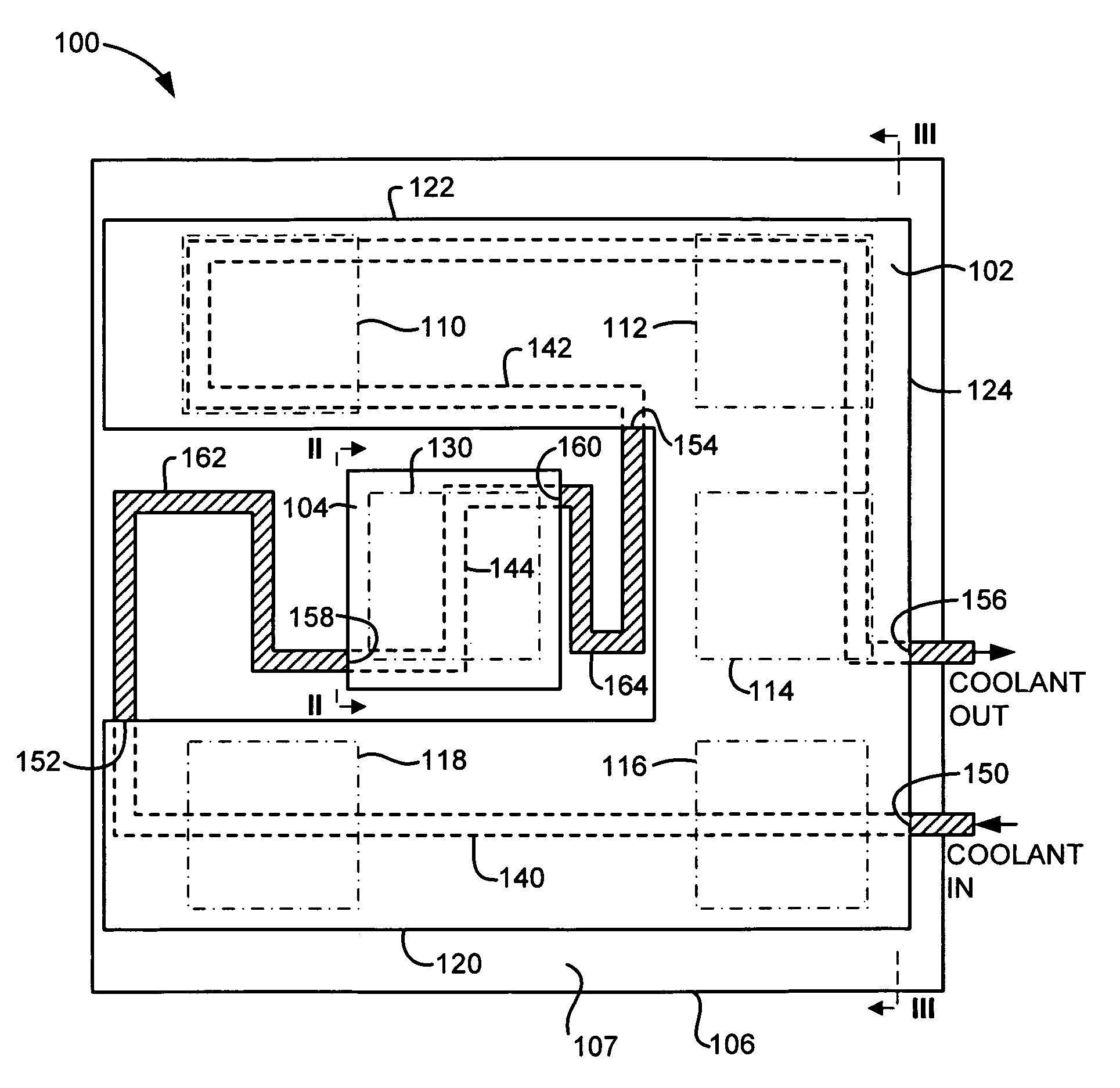
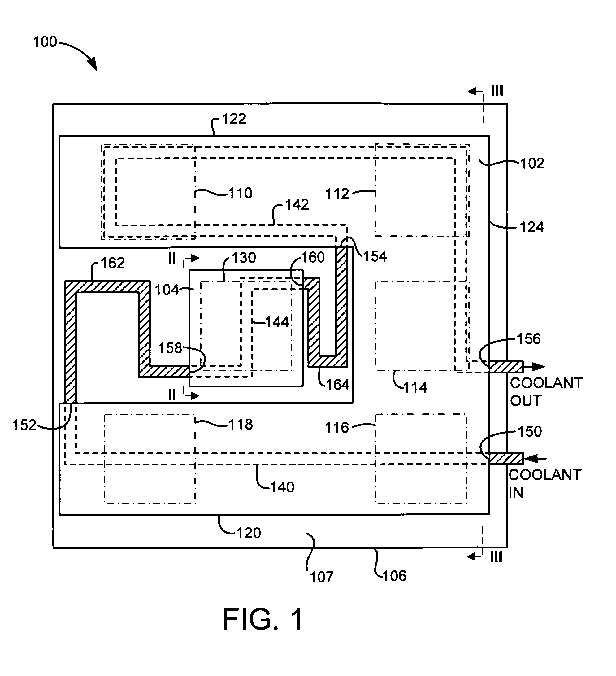
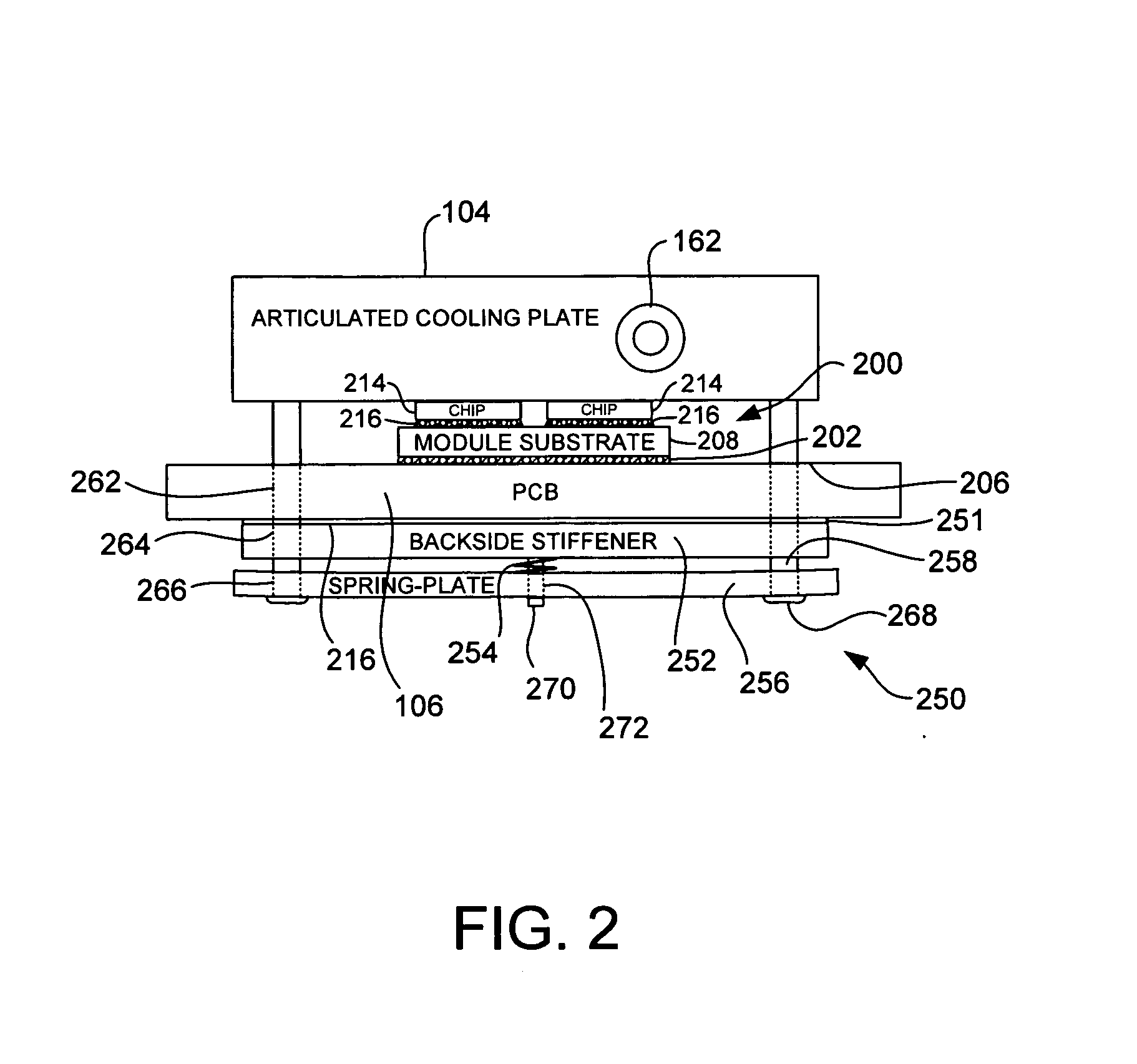
[0023]In accordance with the preferred embodiments of the present invention, a cooling plate assembly for transferring heat from electronic components mounted on a circuit board includes both fixed and articulated interfaces. A fixed-gap coldplate is positioned over and in thermal contact with (e.g., through an elastomerically compressive pad thermal interface material) electronic components mounted on the circuit board's top surface. An articulated coldplate is positioned over and in thermal contact with at least one electronic component mounted on the circuit board's top surface. In the preferred embodiments, the articulated coldplate is spring-loaded against one or more high power processor components having power dissipation greater than that of the electronic components under the fixed-gap cooling plate. Thermal dissipation channels in the coldplates are interconnected by flexible tubing, such as copper tubing with a free-expansion loop. In the preferred embodi...


PUM

PropertyMeasurementUnit
power dissipationaaaaaaaaaa
poweraaaaaaaaaa
thicknessaaaaaaaaaa

Abstract

A cooling plate assembly for transferring heat from electronic components mounted on a circuit board includes both fixed and articulated interfaces. A fixed-gap coldplate is positioned over and in thermal contact with (e.g., through an elastomerically compressive pad thermal interface material) electronic components mounted on the circuit board's top surface. An articulated coldplate is positioned over and in thermal contact with at least one electronic component mounted on the circuit board's top surface. In the preferred embodiments, the articulated coldplate is spring-loaded against one or more high power processor components having power dissipation greater than that of the electronic components under the fixed-gap cooling plate. Thermal dissipation channels in the coldplates are interconnected by flexible tubing, such as copper tubing with a free-expansion loop. In the preferred embodiments, the coldplates and the flexible tubing are connected to define a portion of a single flow loop used to circulate cooling fluid through the coldplates.

Description

BACKGROUND OF THE INVENTION[0001]1. Field of Invention[0002]The present invention relates in general to the field of electronic packaging. More particularly, the present invention relates to electronic packaging that removes heat from a plurality of electronic components using a cooling plate assembly with both fixed and articulated interfaces.[0003]2. Background Art[0004]Electronic components, such a microprocessors and integrated circuits, must operate within certain specified temperature ranges to perform efficiently. Excessive temperature degrades electronic component functional performance, reliability, and life expectancy. Heat sinks are widely used for controlling excessive temperature. Typically, heat sinks are formed with fins, pins or other similar structures to increase the surface area of the heat sink and thereby enhance heat dissipation as air passes over the heat sink. In addition, it is not uncommon for heat sinks to contain high performance structures, such as vapor...

Claims


Application Information

Patent Timeline
Patent Type & Authority Applications(United States)
IPC IPC(8): H05K7/20B21D39/03
CPCH01L23/473H05K1/0206H01L2224/16225Y10T29/49826H01L2924/10253H01L2924/00
Inventor BUTTERBAUGH, MATTHEW ALLENHOLAHAN, MAURICE FRANCISLYON, TERRY L.MOTSCHMAN, DAVID ROY
Owner IBM CORP
Why Eureka
Try Eureka