Low pressure section steam turbine bucket

a steam turbine and low-pressure section technology, applied in waterborne vessels, machine/engines, blade accessories, etc., can solve the problems of high vibration stress, high operating stress, and high service requirements of steam turbine buckets, and achieve low vibration stress, improved dampening characteristics, and improved stiffness

Inactive Publication Date: 2009-08-27
GENERAL ELECTRIC CO
View PDF20 Cites 20 Cited by
  • Summary
  • Abstract
  • Description
  • Claims
  • Application Information

AI Technical Summary

Benefits of technology

[0010]Accordingly, a need exists in the art for a last stage bucket having longer van...

Problems solved by technology

The service requirements of steam turbine buckets can be complex and demanding.
Last stage buckets, in particular, are routinely exposed to a variety of severe operating conditions, including the corrosive environments caused by high moisture and the carry-over from the boiler.
Such conditions can lead to serious corrosion and pitting problems with the bucket material, particularly in longer, last stage turbine buckets having vane lengths of 40 inches or greater.
The development of larger last stage turbine buckets, e.g., those with vane lengths of about 40 inches or more, poses additional design problems due to the inertial loads that often exceed the strength capability of conventional bucket materials such as Ti6Al4V and iron-based alloys.
Steam turbine buckets, particularly last stage buckets with longer vanes, experience higher tensile loadings and thus are subject to cyclic stresses which, when combined with a corrosive environment, can be very damaging to the bucket over long periods of use.
As a result, water droplet impact erosion of the bucket material often occurs in the last stage.
Such erosion reduces the useable service life of the bucket and the efficiency of the steam turbine as a whole.
In the past, it has been difficult to find bucket materials capable of meeting all of the mechanical requirements for different end use applications, particularly mechanical designs in which longer vane buckets, i.e., those having vane lengths about 40 inches or more, have been employed.
Invariably, the lo...

Method used


Image

  • Low pressure section steam turbine bucket
  • Low pressure section steam turbine bucket
  • Low pressure section steam turbine bucket

Examples


Embodiment Construction

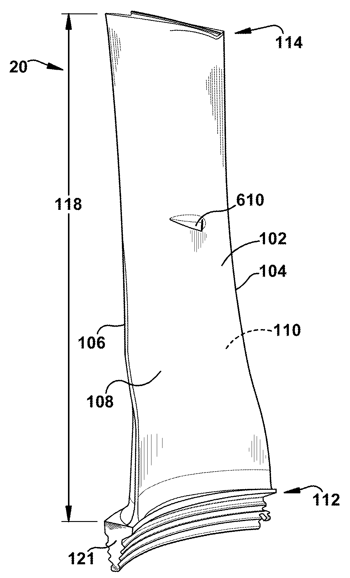
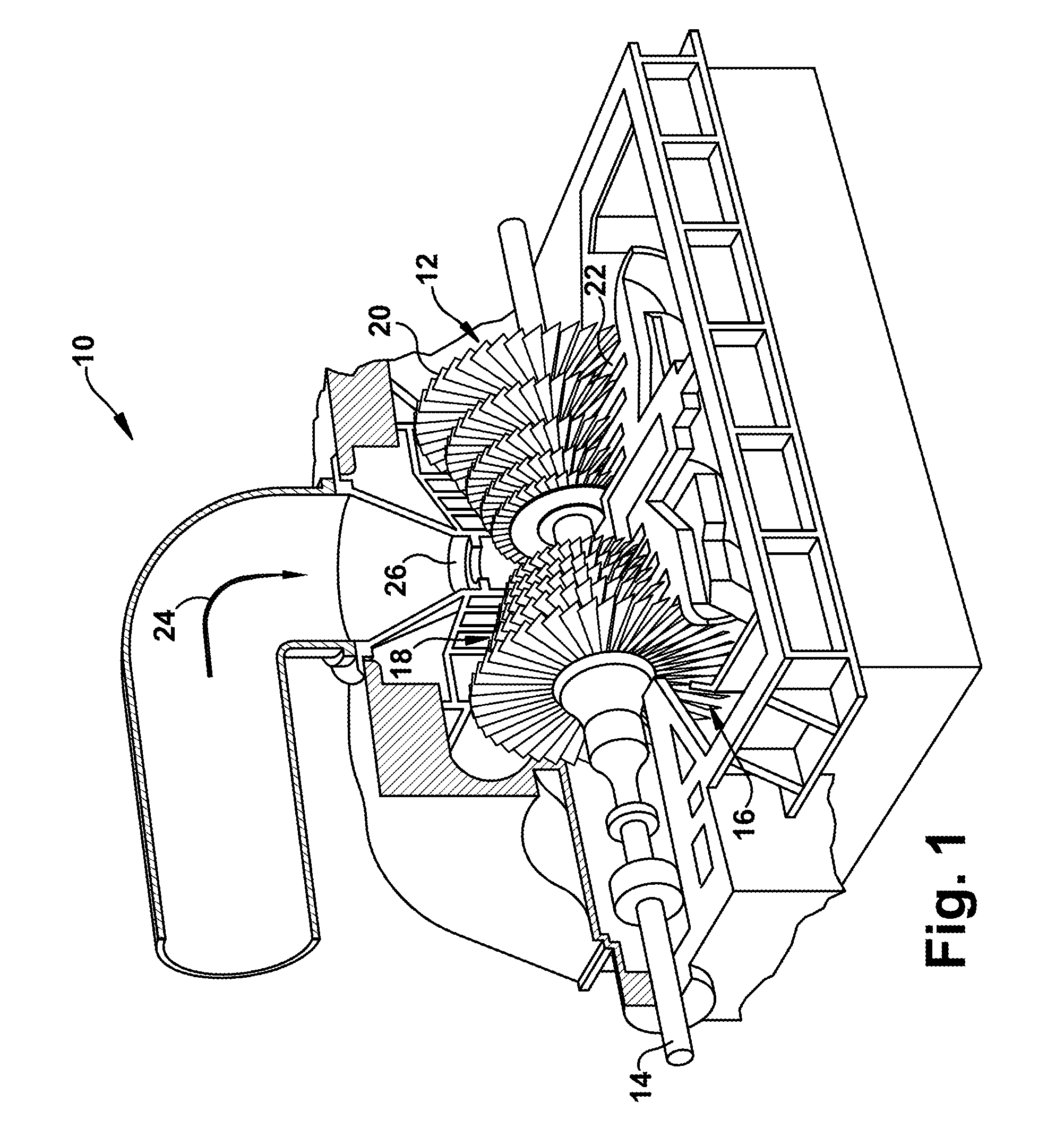
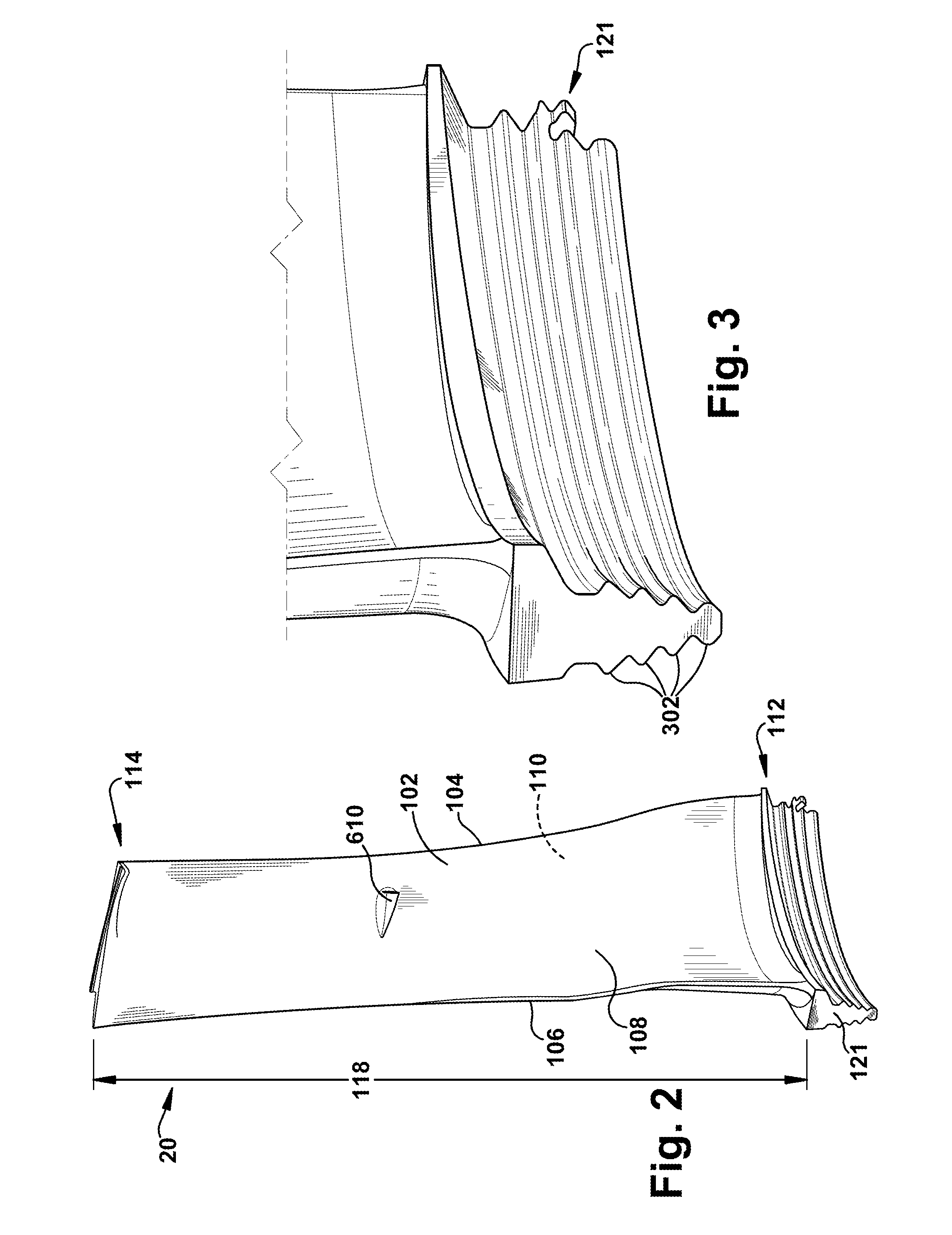
[0020]FIG. 1 is a perspective partial cut away view of a steam turbine 10 including a rotor 12 that includes a shaft 14 and a low-pressure (LP) turbine 16. LP turbine 16 includes a plurality of axially spaced rotor wheels 18. A plurality of buckets 20 are mechanically coupled to each rotor wheel 18. More specifically, buckets 20 are arranged in rows that extend circumferentially around each rotor wheel 18. A plurality of stationary nozzles 22 extend circumferentially around shaft 14 and are axially positioned between adjacent rows of buckets 20. Nozzles 22 cooperate with buckets 20 to form a turbine stage and to define a portion of a steam flow path through turbine 10.

[0021]In operation, steam 24 enters an inlet 26 of turbine 10 and is channeled through nozzles 22. Nozzles 22 direct steam 24 downstream against buckets 20. Steam 24 passes through the remaining stages imparting a force on buckets 20 causing rotor 12 to rotate. At least one end of turbine 10 may extend axially away fro...


PUM

PropertyMeasurementUnit
Lengthaaaaaaaaaa
Fractionaaaaaaaaaa
Fractionaaaaaaaaaa

Abstract

A bucket for use in the low-pressure section of a steam turbine engine is provided. The bucket has a vane length of at least about 45 inches. The bucket is comprised of a dovetail section disposed near an inner radial position of the bucket, a tip shroud disposed near an outer radial position of the bucket and a part span shroud disposed at an intermediate radial position. The intermediate radial position is located between the inner and outer radial positions. The bucket is comprised of a titanium-based alloy having between about 2% and about 6.25% by weight aluminum, up to about 3.5% vanadium, up to about 2.25% tin, up to about 2.25% zirconium, between about 1.75% and about 5.0% molybdenum, up to about 2.25% chromium, up to about 0.7% silicon and up to about 2.3% iron, with the balance being titanium.

Description

BACKGROUND OF THE INVENTION[0001]The present invention relates to high strength buckets for use in the last stage of steam turbine engines. Specifically, the invention relates to the application of certain titanium-based alloys for use in making high strength, last stage turbine buckets having vane lengths of about 45 inches or greater.[0002]It is generally recognized that the performance of a steam turbine is greatly influenced by the design and performance of later stage buckets operating at reduced steam pressures. Ideally, the last stage bucket should efficiently use the expansion of steam down to the turbine exhaust pressure, while minimizing the kinetic energy of the steam flow leaving the last stage.[0003]The service requirements of steam turbine buckets can be complex and demanding. Last stage buckets, in particular, are routinely exposed to a variety of severe operating conditions, including the corrosive environments caused by high moisture and the carry-over from the boil...

Claims


Application Information

Patent Timeline
IPC IPC(8): F01D5/14F01D5/22
CPCC22C14/00F01D5/14F01D5/22F01D5/28F05D2220/31F05D2300/1614F05D2300/121F05D2300/132F05D2300/131F05D2300/13F05D2300/11
Inventor DEMANIA, ALAN R.MUJEZINOVIC, AMIR
Owner GENERAL ELECTRIC CO
Why Eureka
Try Eureka