Method for manufacturing the rotor assembly of a rotating vacuum pump

a technology of rotary vacuum pump and rotor assembly, which is applied in the direction of manufacturing stator/rotor bodies, machines/engines, liquid fuel engines, etc., can solve the problems of reducing the tensile yield point, reducing the number of rejected pieces, and reducing the overall manufacturing cost. , the effect of easy reversibility

Active Publication Date: 2009-08-27
AGILENT TECH INC
View PDF3 Cites 19 Cited by
  • Summary
  • Abstract
  • Description
  • Claims
  • Application Information

AI Technical Summary

Benefits of technology

[0026]The present invention is directed to the method for manufacturing the rotor assembly and the rotor assembly produced by this method. According to the invention, the only thermal treatment envisaged during the coupling step between the rotor and the shaft is heating the steel shaft, resulting in a reduction in the process costs.
[0028]Advantageously, according to the method of the invention, the process of coupling the rotor and the supporting shaft is easily reversible, by cooling the same rotor. In this manner, it is possible to recover the rotor and the supporting shaft in case of alignment errors made during the coupling step, thereby reducing the number of rejected pieces and consequently reducing the overall manufacturing costs.

Problems solved by technology

Due to the higher thermal expansion coefficient of aluminium with respect to steel, the increase in the temperature of the rotor of aluminium during its operation will result in a loss of interference between the female cavity in the rotor and the male projection in the shaft, with a consequent risk of vibrations and misalignments or loss of the axial constraint of the rotor.
First, heating the aluminium rotor to a high temperature entails a deterioration of the mechanical characteristics, in particular of the tensile yield point.
Second, in order to maintain a good interference in any operating condition, that is for instance even when the rotor operates at high temperatures because of the heating caused by the friction with gas being pumped, it is necessary to provide for a very high interference at nominal conditions, that is when the rotor is stationary, with a resulting risk of a stress close to the yield point of the material of the rotor.
Third, since heating the rotor is not sufficient per se, and also cooling the steel shaft to a temperature well below 0° C. is required, use of expensive equipment using liquid nitrogen is necessary.
A further drawback of the prior art described above is related to the irreversibility of the coupling process, so that any error made while manufacturing the rotor assembly entails rejecting the defective piece.
This latter drawback is even more serious if one considers that it takes place at the end of the manufacturing process of the rotor assembly and entails rejection of already finished, expensive semi-manufactured pieces.
Both methods described above have a considerable drawback that they require heating the aluminium alloy forming the rotor to a very high temperature, with a consequent risk of deterioration of the mechanical properties.
This is a very complex method, which demands the use of specific equipment.
Moreover, it would not be suitable for applications in the field of turbomolecular pumps for several reasons: first, the presence of oil or water residuals could pollute the environment under vacuum; moreover, the presence of a duct for introducing pressurised fluid would result in an unbalance in the mass distribution of the shaft, with very serious consequences, taking into account the extremely high rotation speed of the rotor.
Such a method has however the drawback of being irreversible, due to the brazing, whereby it does not allow recovering faulty pieces.
Moreover, also in this case, application to turbomolecular vacuum pumps would be impossible, since the introduction of loose brazing material and the subsequent chaotic distribution of said material between the shaft and the rotor could result in lack of uniformity in the mass distribution, and hence to unbalances that, taking into account the high rotation speeds, could have dreadful consequences when the rotor is rotated at extremely high speed.

Method used


Image

  • Method for manufacturing the rotor assembly of a rotating vacuum pump
  • Method for manufacturing the rotor assembly of a rotating vacuum pump
  • Method for manufacturing the rotor assembly of a rotating vacuum pump

Examples


Embodiment Construction

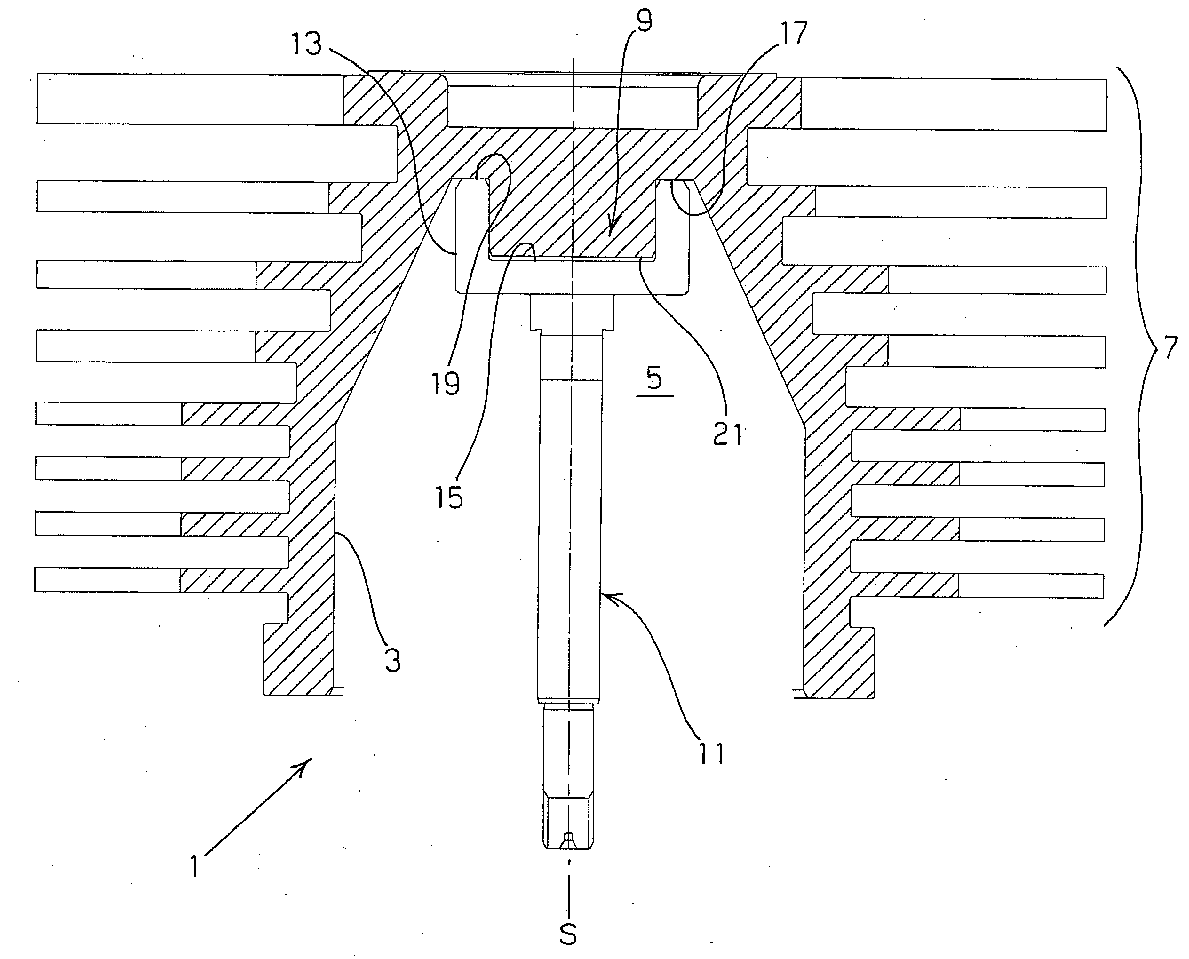
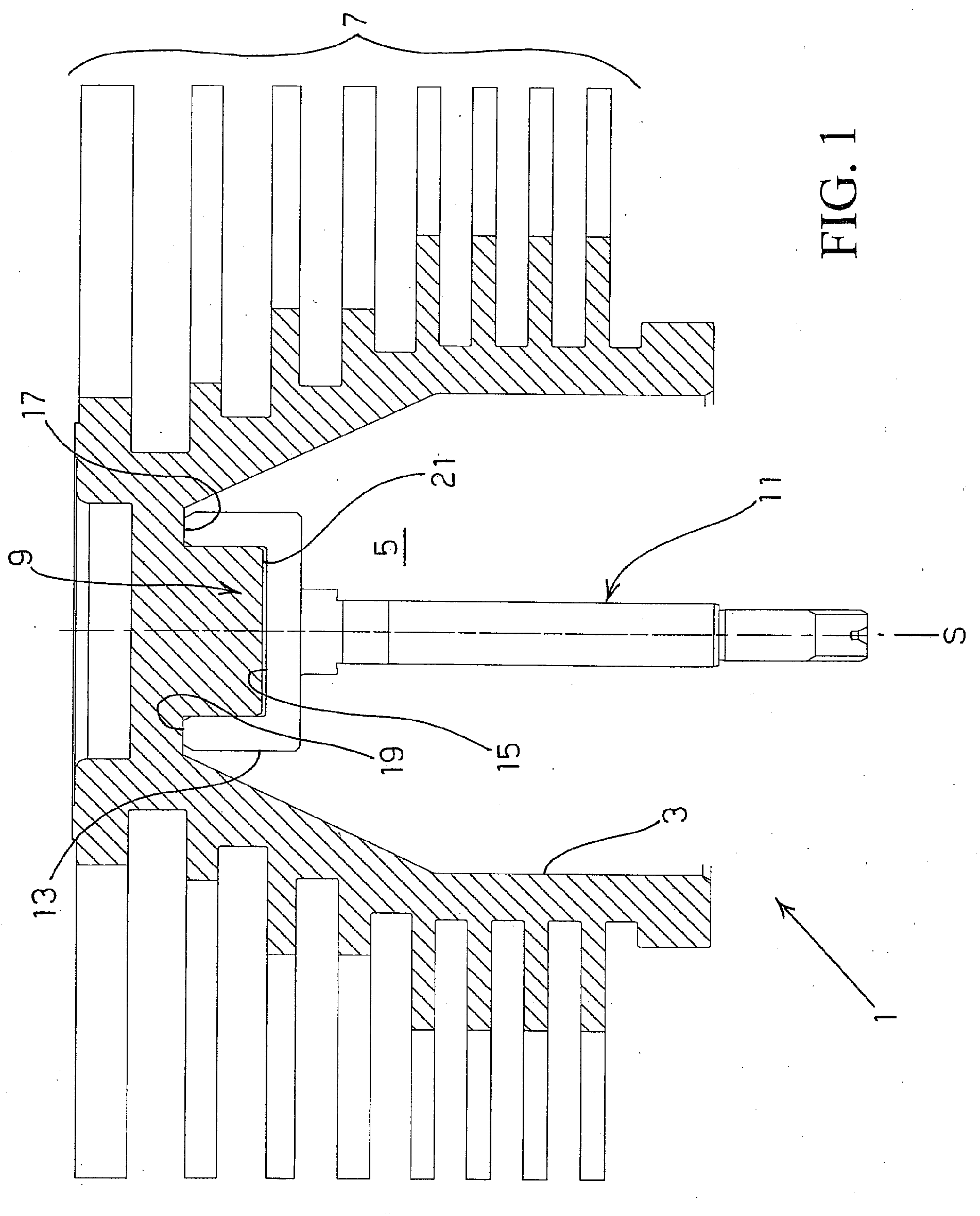
[0032]Referring to FIG. 1, there is shown a rotor assembly 1 comprising a rotor 3 and a supporting shaft 11. In the illustrated example, which relates to a turbomolecular pump, rotor 3 includes a central bell-shaped cavity 5, intended to house the electric motor of the pump, and a plurality of parallel rotor discs 7, intended to cooperate with corresponding stator discs formed on the stationary part of the pump in order to form pumping stages.

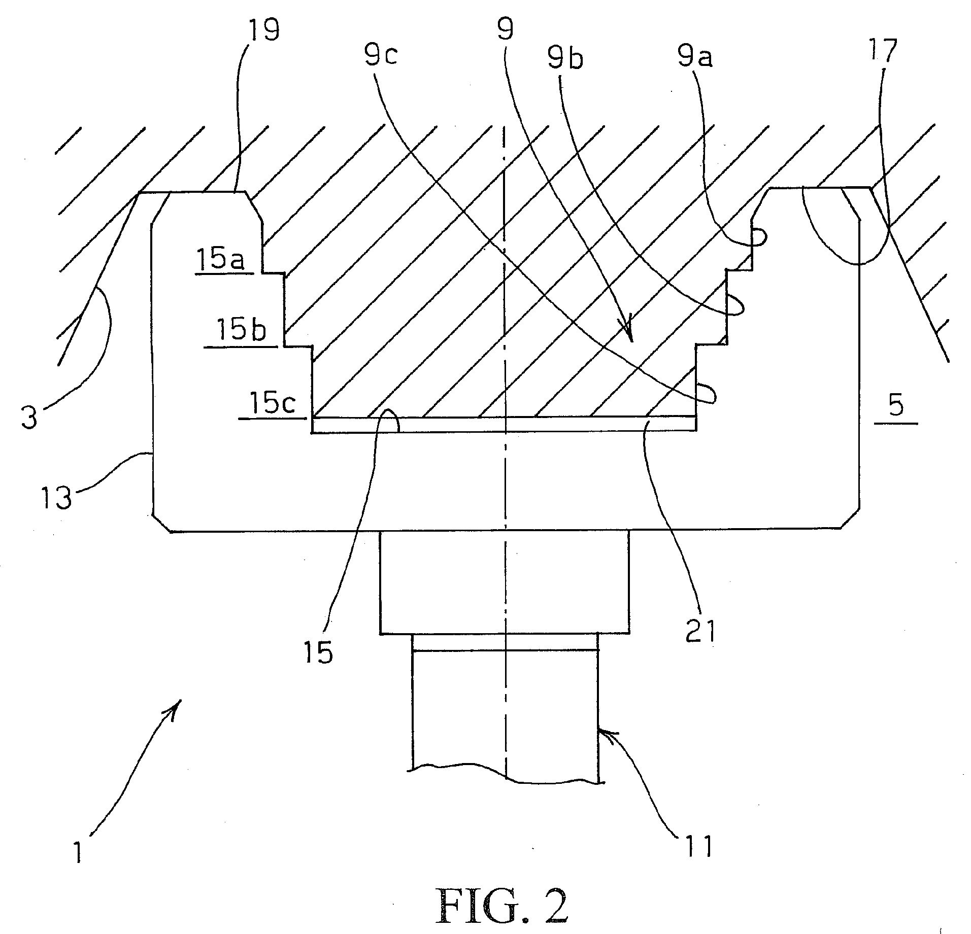
[0033]According to the invention, rotor 3 further includes a male projection 9 centrally and axially extending towards the interior of bell-shaped cavity 5. In the illustrated example, projection 9 is cylindrical, but it could even have a different shape, for instance a frusto-conical shape. However, it is evident that, since the rotor assembly is to rotate about axis S of supporting shaft 11 at very high speed while keeping a perfect alignment, it is preferable that the projection has the shape of a solid of revolution, so as to perturb as lit...


PUM

PropertyMeasurementUnit
temperatureaaaaaaaaaa

Abstract

A rotor assembly for rotary vacuum pumps has improved mechanical characteristics and low manufacturing cost due to a one-step thermal coupling of a rotor having a male axial projection and its supporting shaft having an end portion comprising a female cavity with a shape and size for receiving the male projection with interference at an ambient temperature. The rotor and the shaft are made of different materials. Heating of the end portion of the shaft provides expansion of the female cavity and allows for inserting the mail projection of the rotor into the female cavity of the shaft. By cooling the end portion to the ambient temperature the contraction of the cavity is obtained forming fixed interference coupling between the shaft and the rotor, where the end portion of the shaft contracts and compresses about the male axis projection of the rotor.

Description

CROSS REFERENCE TO RELATED APPLICATIONS[0001]The subject patent application claims priority to European Patent Application No. 08425120.6 filed in the European Patent Office on Feb. 27, 2008.FIELD OF THE INVENTION[0002]The present invention relates to a method of manufacturing the rotor assembly of a rotary vacuum pump. More particularly, the invention relates to a method of manufacturing the rotor assembly of a turbomolecular rotary vacuum pump.[0003]Generally, the term “rotor assembly”, as used herein, means the whole of the rotor or impeller of a rotary vacuum pump and the supporting shaft associated therewith.[0004]Examples of turbomolecular pumps are disclosed in the European patents EP 0773367 and EP 1484508.[0005]In the field of turbomolecular vacuum pumps, in some cases, especially in small size pumps, the rotor and its supporting shaft can be made of the same material, e.g. an aluminium alloy, and the rotor assembly can therefore be manufactured as an integral piece. Yet, i...

Claims


Application Information

Patent Timeline
Patent Type & Authority Applications(United States)
IPC IPC(8): F01D5/30B21D53/78
CPCF04D19/042Y10T29/49316Y10T29/49012F04D29/266
Inventor BUCCHERI, GIANLUCACRISI, ALDOPANDOLFO, VINCENZO
Owner AGILENT TECH INC
Why Eureka
Try Eureka