Mechanical press drive system

a drive system and mechanical press technology, applied in forging presses, forging/pressing/hammering apparatuses, shape safety devices, etc., can solve the problems of low production rate, long cycle time, low speed, etc., and achieve the effect of reducing setup times, improving controllability, and more flexibility

Inactive Publication Date: 2009-09-03
ABB RES LTD
View PDF9 Cites 19 Cited by
  • Summary
  • Abstract
  • Description
  • Claims
  • Application Information

AI Technical Summary

Benefits of technology

[0033]A disadvantage of today's large mechanical presses is that production speed of a pressed or stamped part is limited by the fixed speed profile of the actual pressing process. This limitation has been reduced by the introduction of a servo press, which also eliminates the need for the expensive clutch and brake. However, the servo press requires a large motor and power converter, perhaps up to five times larger than that of a converter for the fully mechanical press. The servo press may then require large investments to establish a robust grid connection or else an electrical energy storage device.
[0075]For example, line coordination may be carried out by controlling such a line using a single controller, due to the improved controllability of the presses according to an embodiment of the invention. Coordination or optimisation may be achieved in part by adapting speed during opening / closing a press (while for example maintaining a required speed and energy output during the pressing / stamping part of the cycle), resulting in cycle times which may be reduced dependent on parameters such as: a state of a downstream process; or a state of an upstream process or another consideration such as overall power consumption; reduced energy consumption; smoothing power consumption peaks in the press line.

Problems solved by technology

Thus, if pressing has to be done at a low speed (for quality reasons), the complete operation will occur at low speed.
This results in a long cycle time, and therefore, a low production rate.
However, the servo press requires a large motor and power converter (approx. five times larger than the fully mechanical press).
Although much smaller than the flywheel in the fully mechanical solution, this inertia or small flywheel requires high peak power and transfer of a large amount of energy to accelerate and decelerate.
However, servo motor presses may have a high peak power consumption for some products, for example products requiring deep drawing.

Method used


Image

  • Mechanical press drive system
  • Mechanical press drive system
  • Mechanical press drive system

Examples


Embodiment Construction

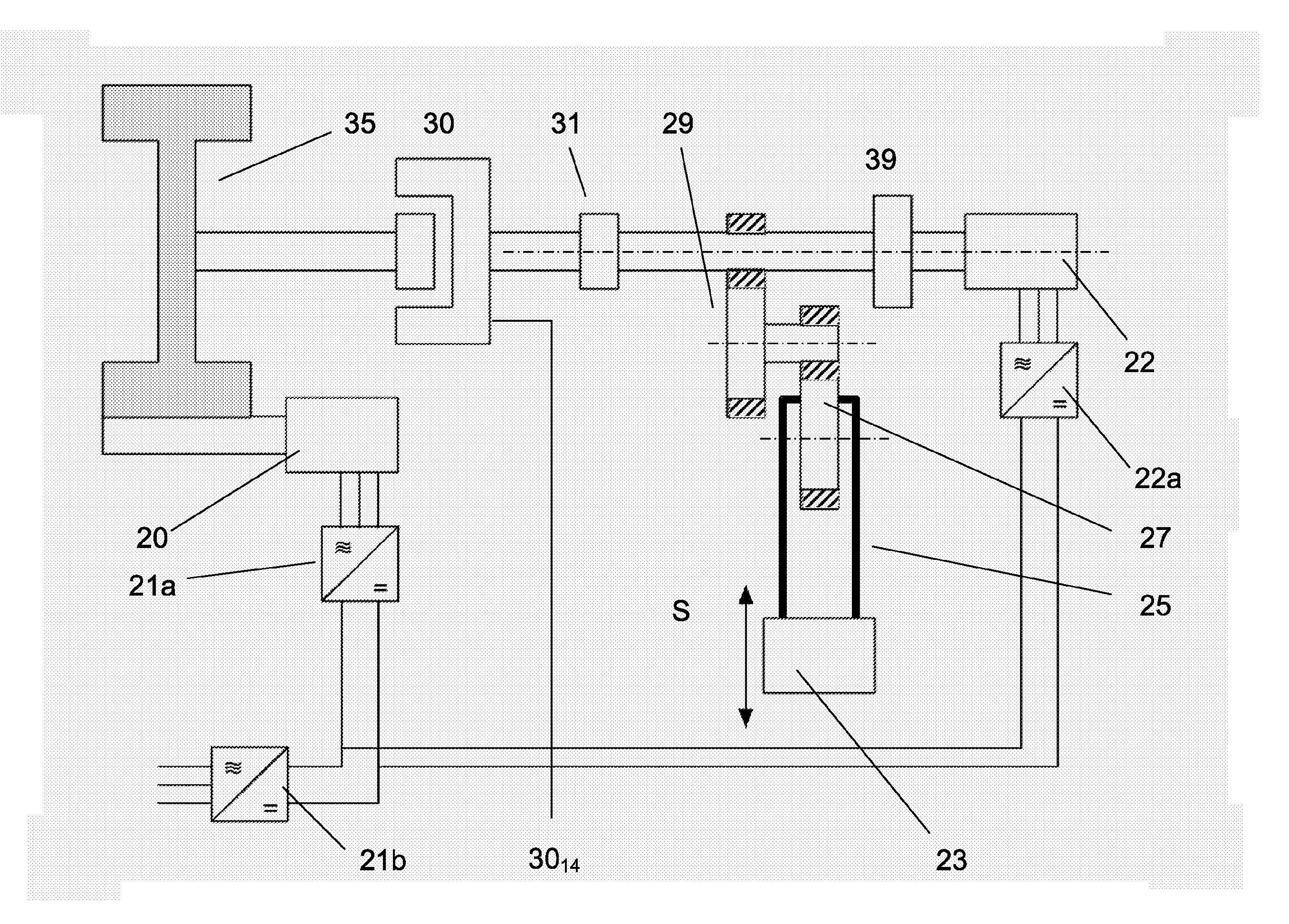
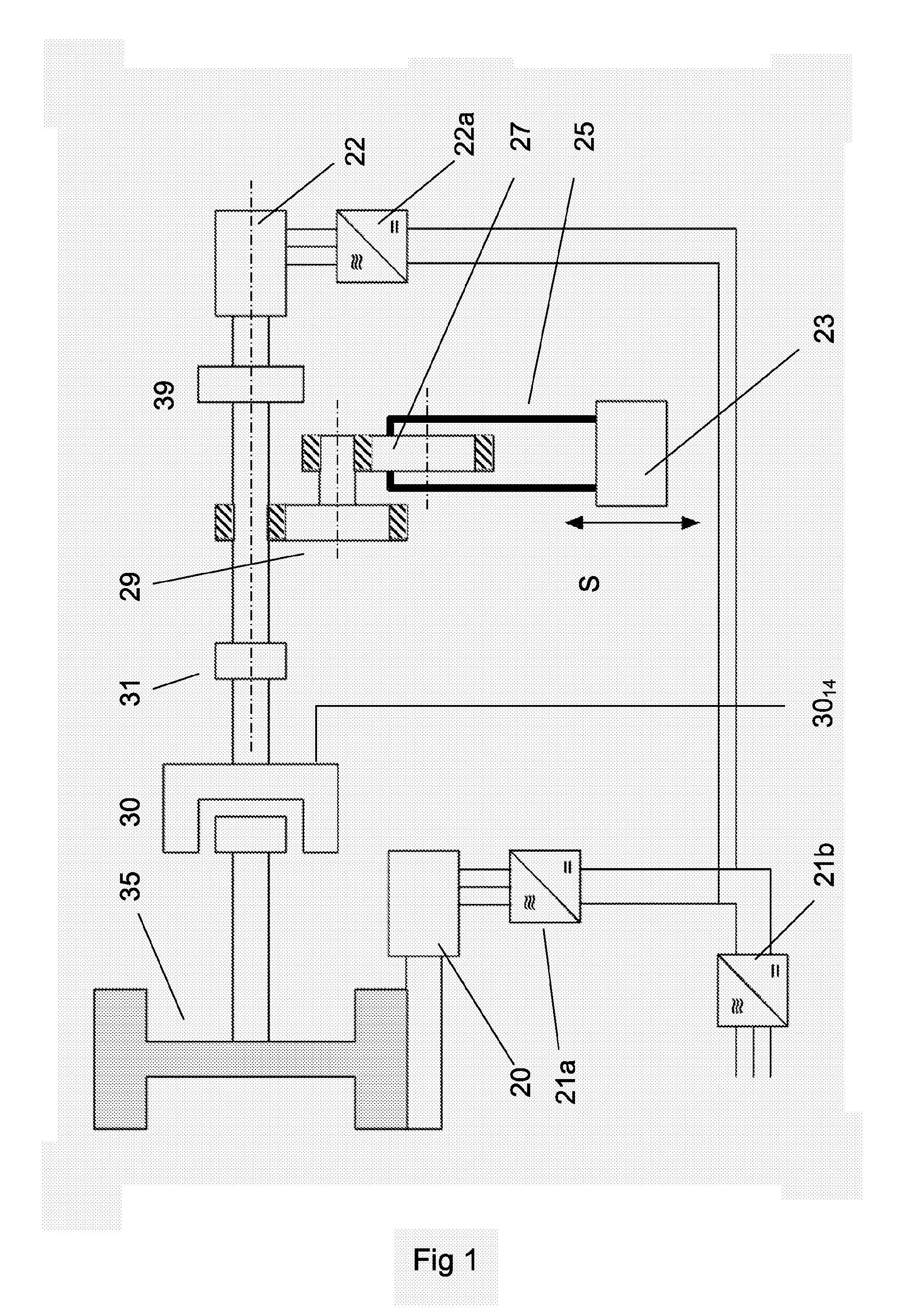
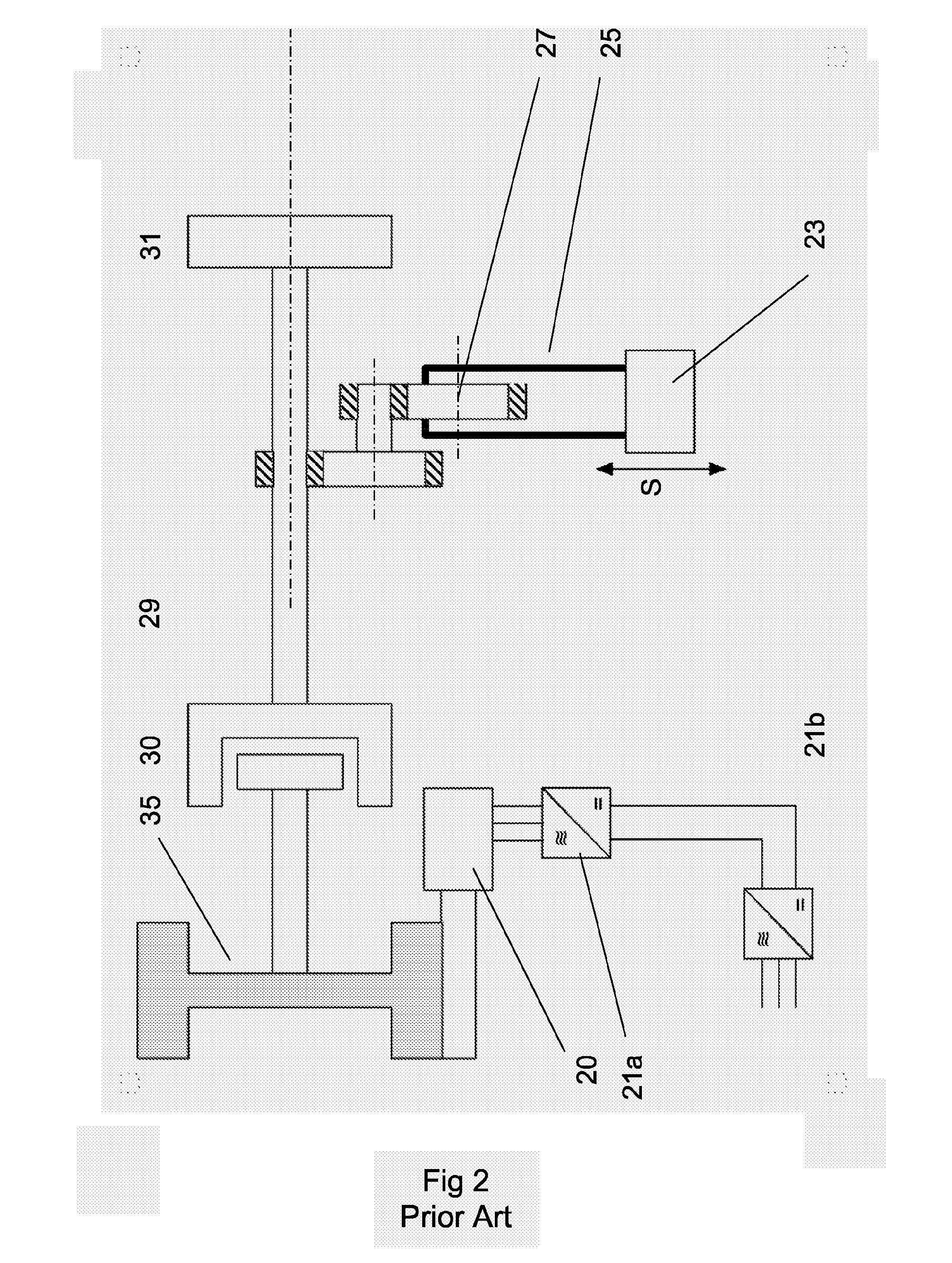
[0088]FIG. 1 shows a schematic layout for an improved mechanical press according to an embodiment of the invention. It shows a slide or press ram 23 which is driven in a up-and-down motion S by an eccentric drive wheel 27. The eccentric drive wheel is in turn driven by a press gear mechanism 29 each part of which is shown in a simplified cross section in which gear teeth are indicated by cross-hatching. Flywheel 35 is driven by a drive motor 20. During the pressing stage, the clutch 30 between flywheel 35 and press gear mechanism 29 is engaged (E). The numbering in FIG. 1 is essentially the same as the numbering in Prior Art FIG. 2 for the same components.

[0089]In FIG. 1 a second drive motor or actuator, such as electric motor 22, is arranged connected to the press gear mechanism 29. An optional second gearbox or other transmission means 39 is shown arranged between the second drive motor and the press gear 29. During the complete press cycle, the second motor is normally connected ...


PUM

PropertyMeasurementUnit
crank angle rotationaaaaaaaaaa
crank angleaaaaaaaaaa

Abstract

A method for operating a mechanical press including an electric drive motor, a drive control for controlling the motor, a ram, a flywheel, a clutch and a member for translating rotational motion of the flywheel in a first rotation direction into a linear motion of the ram arranged to be lowered and raised along a linear path for operating the press to carry out a press production cycle. The press cycle includes a pressing part and one or more non-pressing parts. The press includes a second drive motor or actuator arranged connected to the ram and by providing a control output to the drive control means, the speed of the second drive motor is made variable during at least one part of the press production cycle. The press may be reversed between production cycles. A press and system including such a press.

Description

TECHNICAL FIELD[0001]The invention concerns a mechanical press of the type used for pressings, stamping or punching of metal parts from blanks. In particular, the invention discloses a mechanical press driven at least in part by an electric motor with an improved system of controlling transmission of power from a drive system to the ram of the press.TECHNICAL BACKGROUND[0002]Mechanical presses are commonly used to produce stamped car parts from steel blanks. Today's large mechanical presses are driven by a flywheel. The function of the flywheel is to store the necessary energy to carry out a pressing operation. A motor drives the flywheel so that before the start of a press operation the flywheel is rotating at the speed at which the pressing will occur. A schematic diagram for a typical mechanical press with a flywheel is shown in FIG. 2 (Prior Art). To start the press operation, a clutch is engaged, which connects the press (until then standing still) to the flywheel. The press th...

Claims


Application Information

Patent Timeline
Patent Type & Authority Applications(United States)
IPC IPC(8): B30B1/00
CPCB30B1/266B30B15/148B30B15/14B30B1/26
Inventor BOSGA, SJOERD GHOSINI, FALAHSEGURA GOLORONS, MARC
Owner ABB RES LTD
Why Eureka
Try Eureka