
Motorized bicycle

a motorized bicycle and electric technology, applied in the direction of motorcycles, riders, vehicles, etc., can solve the problems of heavy gearboxes, inefficient systems, and the rider must pedal when the motor is on, and achieve the effect of greatly reducing chain wear

Inactive Publication Date: 2009-09-03
YEE RAYMOND
View PDF34 Cites 20 Cited by
  • Summary
  • Abstract
  • Description
  • Claims
  • Application Information

AI Technical Summary

Benefits of technology

[0012]Accordingly, the need exists for an electric powered bicycle that includes at least one of the following advantages. Firstly, one advantage is a simple, inexpensive multi-speed drive wheel that can be efficiently driven by a motor. Another advantage is a speed shifting apparatus that can be used to shift the multi-speed drive to increase torque multiplication as the bicycle begins to climb steeper hills such that when the hub shifts to larger reductions, the torque required from the motor to climb the hill is reduced and the efficiency increases. Another advantage of the invention is an increase in efficiency with a lighter bicycle. Another advantage of the invention is a drive arrangement that is independent of the bicycle drive where the rider can be assisted while pedaling at any speed or effort while the drive operates at an efficient range. Yet a further advantage is a low polar moment of inertia for the drive wheel so unassisted riding feels similar to a normal bicycle. Another advantage is a motor / drive unit and battery that can be retrofitted to an existing bicycle such that the battery can be in a position that is low and close to the center of the bicycle.
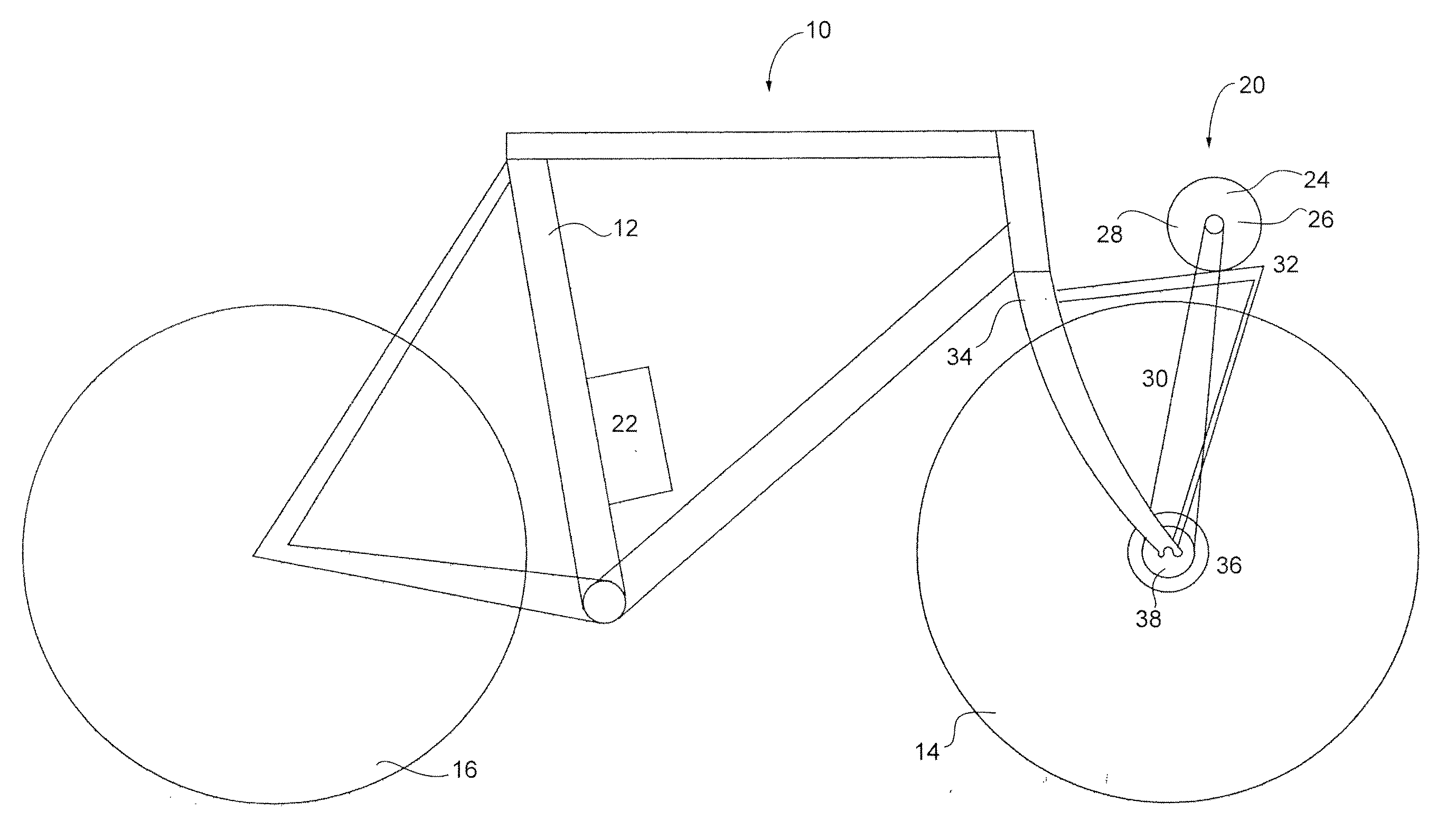
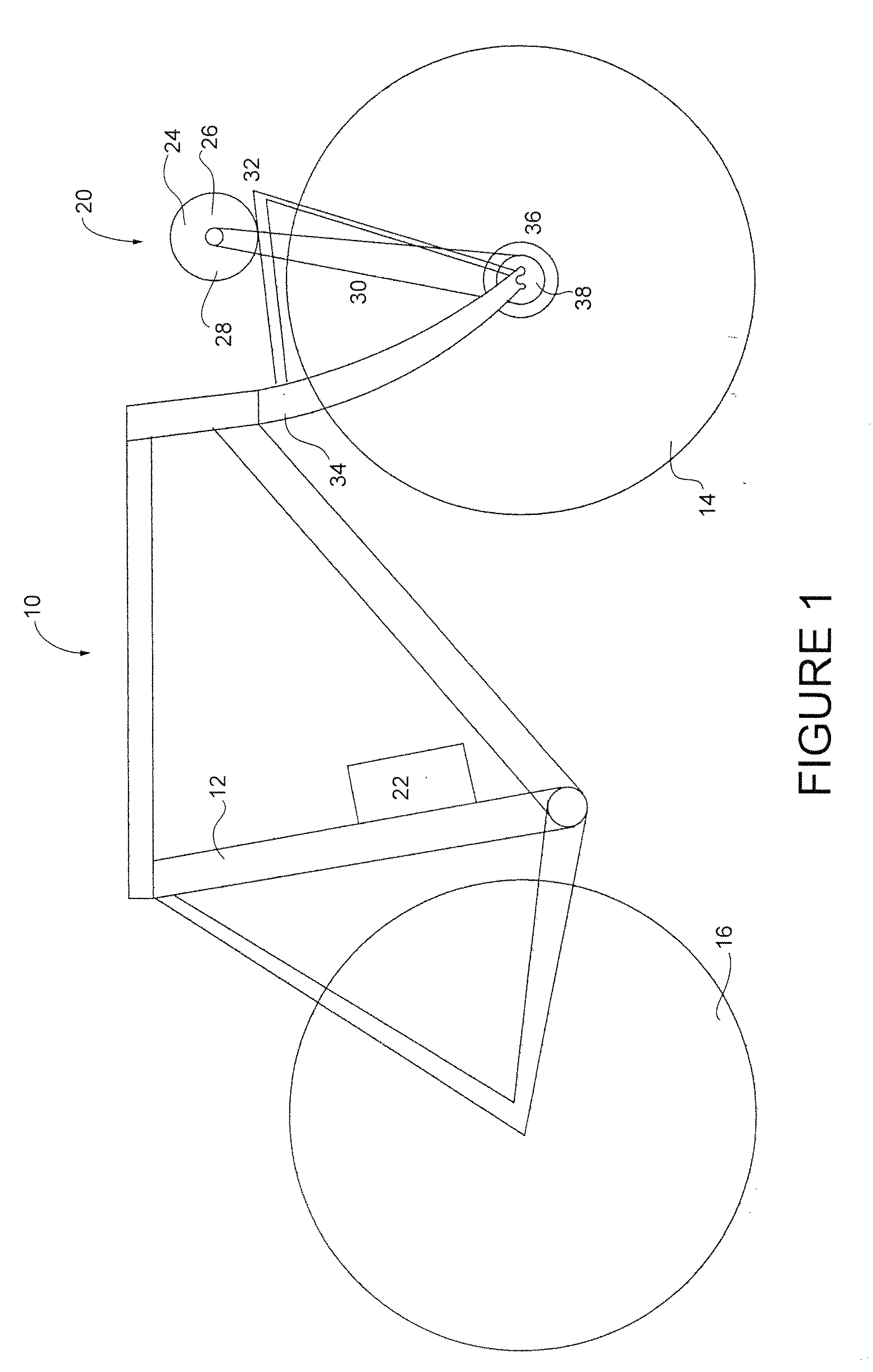
[0013]In a preferred embodiment, a brushless, direct current electric motor is used, but not installed to the wheel as the manufacturer intended. Instead, on a front drive embodiment, the motor is mounted to brackets that are, in turn, mounted to the fork of the bicycle, just forward of the frame. A conventional chain can then be operatively connected around the sprocket(s) to drive the standard internally geared hub in the front wheel. The difference in the size of the sprockets can be adjusted to obtain the desired top speed of the bicycle, depending on the highest gear ratio of the multi-speed hub chosen.
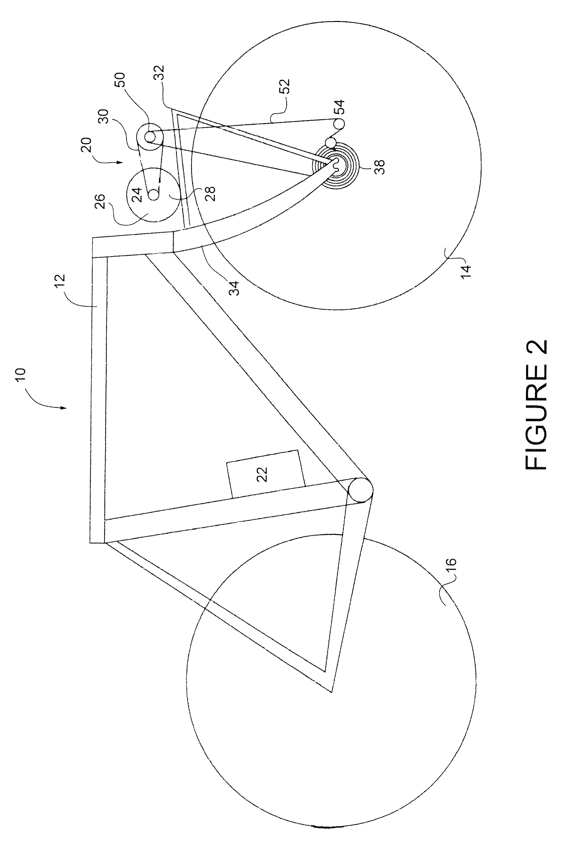
[0014]In another embodiment, such as a rear wheel drive embodiment, a freewheeling sprocket is added to the drive gear of the internally geared rear hub. The standard bicycle drive train is connected to the freewheeling sprocket while the motor drive turns the drive gear. This allows the motor to assist the rider with the motor speed synchronized to the rider. Since the drive freewheels when coasting, the motor offers almost no resistance to rotation when the power is turned off so that the bicycle can be pedaled with almost the same ease as a non-electric bicycle. Further, since the electric motor drives through a different sprocket than the rider, chain wear is greatly reduced.
[0015]In another embodiment, the gear selection is actuated by a standard rear derailleur mounted on the fork. Optionally, the drive gear can be changed to a multiple gear arrangement actuated by a standard bicycle front derailleur.
[0016]In yet another embodiment of this invention the electric motor drives an independent internal multi-geared hub on the rear wheel. The hub is coupled to the rear wheel by a sprocket attached to the hub of the rear wheel.
[0017]Turning to another embodiment of the invention, there is provided a power assist module for a bicycle comprising a power source; a motor, connected to the power source; a gear reduced output drive gear, controlled by motor; a multi-geared hub, mounted on a wheel of the bicycle; and a motor drive system connecting the output drive gear with the multi-geared hub; wherein rotation of the output drive gear by the motor, causes the drive chain to rotate the hub, thereby rotating the wheel of the bicycle.

Problems solved by technology

The cheapest and simplest type of electric drive for a bicycle is a friction drive which is mounted on the front or rear tire however this system is inefficient.
Electric drives through the pedal shaft to the rear wheel are usually heavy, bulky gearboxes with electric motors attached.
The disadvantage of this system is that a rider must pedal when the motor is in operation.
Versions that allow the motor to drive the rear wheel without turning the pedals are available, but they require additional non-standard mechanisms, which increase the cost of the bicycle.
A further disadvantage of this type of drive is that, in high gear, the pedal shaft turns at about one third of the speed of the rear wheel; therefore, the rotational speed of the motor must be reduced by a factor of about three times when driving through the pedal shaft.
Both the additional reduction and the subsequent acceleration add to friction losses and a loss in overall efficiency of the bicycle.
Another disadvantage of drives through the pedal shaft is that the bulky transmission and motor combination around the pedal shaft requires the battery to be relegated to a higher position on the bike frame, away from the center of the bicycle, causing balance problems.
A disadvantage of electric bicycles with drives through the chain to the rear wheel is that they do not allow multiple front sprockets.
The drive gear, typically mounted after the front crank sprocket, shortens the flex length of the chain which can result in the chain wear and dislodging from the electric drive sprocket.
Direct electric drives to the rear wheel take many different forms, but one disadvantage common to all of them is that they require an additional drive chain and sprocket, or belt and pulley combination, in addition to the customary pedal chain and sprocket.
Additional drives systems to the rear wheel are not multi-geared due to the fact that there is no room for the extra gears and left hand drive components are not common.
However they are much larger in diameter and much heavier.
When applied to the front wheel of a bicycle, they create a gyroscopic force that at high speeds makes the bicycle hard to steer and thereby dangerous in some conditions.
This is an undesirable characteristic from a handling and safety point of view.

Method used


Image

  • Motorized bicycle
  • Motorized bicycle
  • Motorized bicycle

Examples


Embodiment Construction

[0029]The present invention is directed at an apparatus and method for adding an electric powered drive to a conventional pedal bicycle. An electric motor with gear selectable reduction is mounted to the drive portion of the hub, so that either the motor or the pedals, independently or in unison, can drive the bicycle. The use of standard readily available components, adaptability to all standard bicycles, improved efficiency over a wide range of speeds and an independent drive offers many advantages over current motorized electric bicycles.

[0030]Turning to FIG. 1, a schematic diagram of a motorized form of transportation, in the form of a motorized bicycle is shown. The motorized bicycle 10 includes a frame 12 along with a pair of wheels, seen as a front wheel 14 and a rear wheel 16. The bicycle 10 will also include other parts such as, but not limited to, pedals or handlebars which are not shown.

[0031]A power assist module 20 is located near the front wheel 14 of the bicycle 10 to...


PUM


Abstract

The invention is directed at a power assist module for a bicycle comprising a power source; a motor, connected to the power source; an output drive gear, controlled by motor through gear reduction; a multi-geared hub, mounted on a wheel of the bicycle; and a motor drive system connecting the output drive gear with the multi-geared hub; wherein rotation of the output drive gear by the motor, causes the drive chain to rotate the hub, thereby rotating the wheel of the bicycle.

Description

CROSS REFERENCE TO RELATED APPLICATIONS[0001]This application claims the benefit of priority of U.S. Provisional Patent Application No. 61 / 032,680 filed Feb. 29, 2008, which is incorporated herein by reference in its entirety.FIELD OF THE INVENTION[0002]The present invention relates in general to electric powered bicycles, and more particularly to an electric powered bicycle having an improved efficiency over a wide speed range.BACKGROUND OF THE INVENTION[0003]Bicycles have been a form of transportation for many years and in some countries, the main mode of transportation. In more recent times, bicycles have been equipped with means to reduce the amount of energy required by the rider to propel the bicycle, such as by adding electric drives. Prior art electric drives for bicycles can be divided into various categories such as a friction drive on the bicycle wheel; an electric through the pedal shaft to the rear wheel; an electric through the chain to the rear wheel; an electric driv...

Claims


Application Information

Patent Timeline
IPC IPC(8): B62K11/00
CPCB62M6/60
Inventor YEE, RAYMOND
Owner YEE RAYMOND
Learn More