Specimen stage

a technology of specimen and stage, applied in the field of specimen stage, can solve the problems of system complication and increased cost, increase production cost, and longer time for temperature control of the upper layer, and achieve the effect of reducing the movement of the stag

Inactive Publication Date: 2009-09-03
HITACHI HIGH-TECH CORP
View PDF4 Cites 17 Cited by
  • Summary
  • Abstract
  • Description
  • Claims
  • Application Information

AI Technical Summary

Benefits of technology

[0016]With the above structure, it becomes possible to reduce the stage move...

Problems solved by technology

Consequently, there are problems of system complication and increased cost.
A cooling substance is introduced into a vacuum, and thus the production cost is increased.
In addition, when stages are provided as multiple layers, it takes a longer time to perform the temperature control of an upper layer portion.
Furthermore, the active brake as described in P...

Method used


Image

  • Specimen stage
  • Specimen stage
  • Specimen stage

Examples


first embodiment

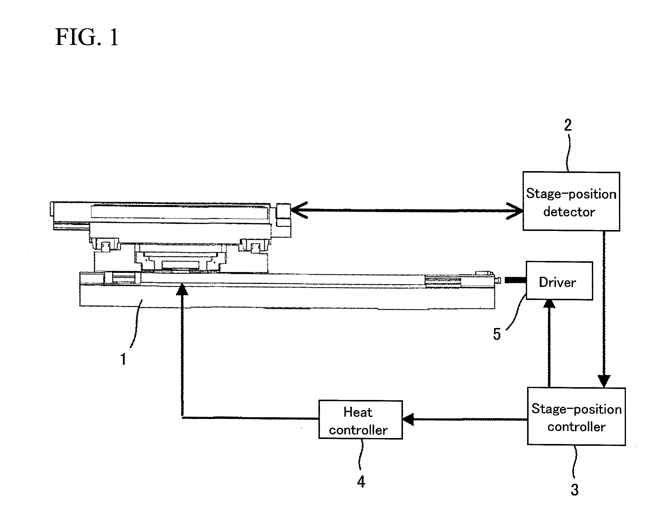
[0029]FIG. 1 is a schematic diagram of a stage unit. The stage unit includes a stage mechanism 1, a stage-position detector 2, a stage-position controller 3, a heat controller 4 and a stage driver 5. Additionally, the stage unit is surrounded by an unillustrated vacuum chamber, and the vacuum chamber is connected to a mirror body of a charged-particle beam apparatus exemplified by an electron microscope. The charged-particle beam apparatus is connected to an unillustrated control device, and the stage-position controller and the like to be described later are controlled by a command initiated from the control device.

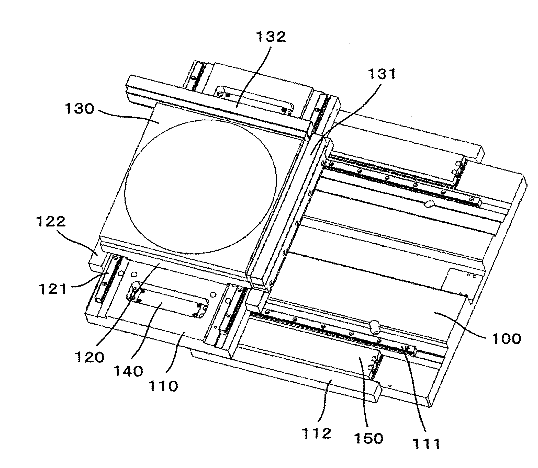
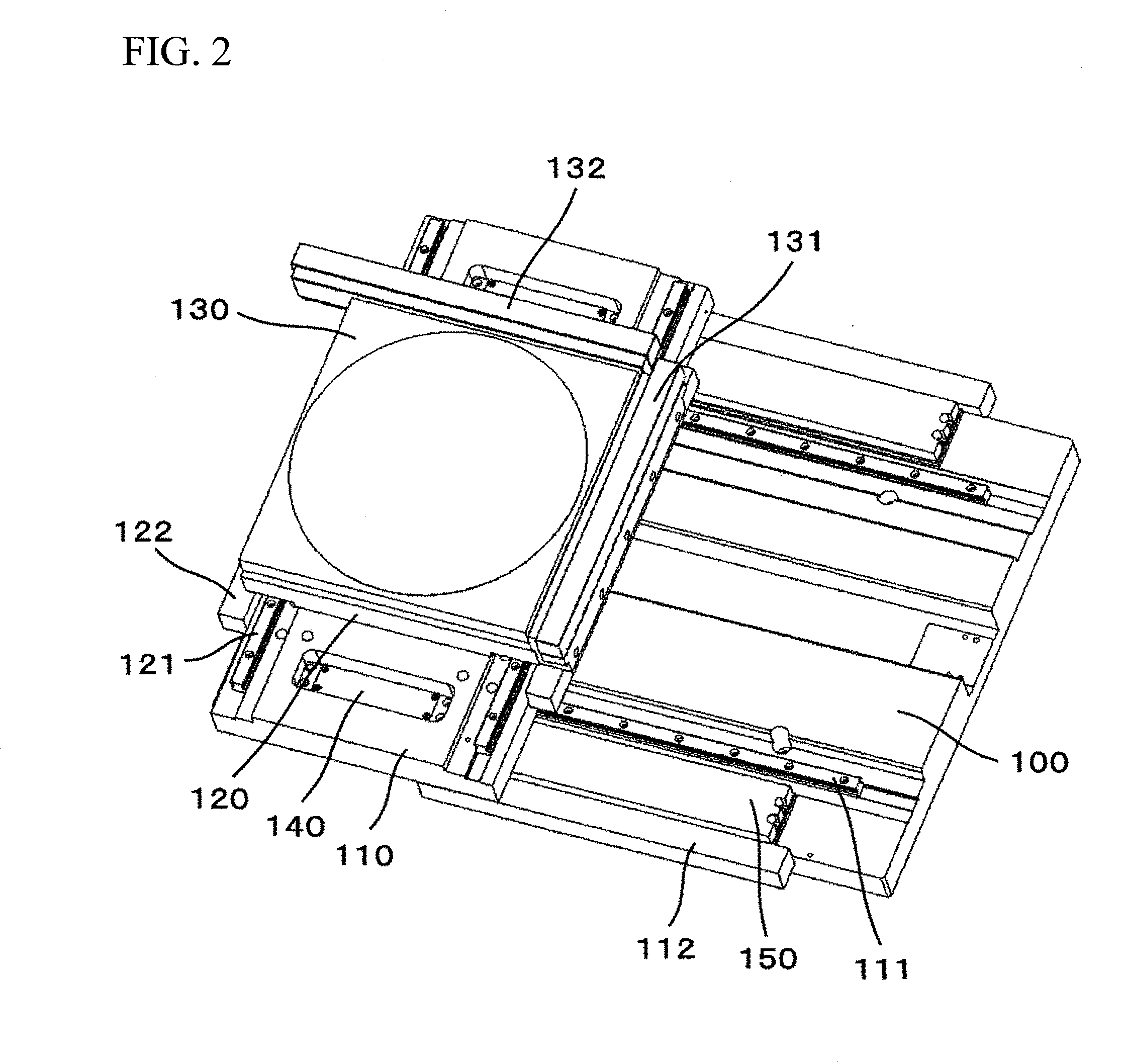
[0030]FIG. 2 is a perspective view of the stage mechanism. The stage mechanism 1 includes: an X table 110 capable of moving on a base 100 in an X direction; a Y table 120 capable of moving on the X table in a Y direction; a specimen holder 130 placed on an upper portion of the Y table; and an X mirror 131 and a Y mirror 132 for measurement by the stage-position detector ...

embodiment 2

[0045]FIG. 6 shows a braking mechanism 140 into which a heat-generating body is inserted. A heat-generating body 160 is inserted into the upper surface of a brake pad 142 of the braking mechanism 140. When the brake pad 142 and the heat-generating body 160 adheres to each other, an attention should be paid not to include air bubbles therebetween in order to efficiently conduct an amount of heat generated by the heat-generating body 160. A heat insulating sheet 161 is introduced into an upper layer of the heat-generating body 160 to efficiently conduct the heat to a surface member. With regard to the flow of the heat control, Steps S11, S12, and S13 of FIG. 5 are altered. In Step S11, the temperature of the brake pad 142 is detected. Then, in Step S12, a thermal analysis is performed on the basis of: the temperature of the brake pad 142, the movement distance, the brake force, the binding condition, and the heat conduction condition. Thereafter, in Step S13, a heat generation amount ...


PUM


Abstract

An object of the present invention is to provide a specimen stage which is simple in structure, and which suppresses a positional shift due to a friction heat caused by a brake or the like. One aspect to achieve the object provides a specimen stage including: a thrust portion thrust by a thrusting member; and a slide surface thrust by the thrust portion. When the specimen stage stops, the specimen stage performs a control in a way that a part of the slide surface in contact with the thrust portion, and/or a portion adjacent to the part or the thrust portion is heated. By heating the part of the slide surface or the like in this manner, a temperature gradient can be suppressed as described above (see FIG. 3).

Description

BACKGROUND OF THE INVENTION[0001]1. Field of the Invention[0002]The present invention relates to a specimen stage, and particularly relates to a stage-positioning mechanism used in a charged particle beam apparatus such as an electron microscope for measurement, inspection or observation in the field of semiconductor device fabrication.[0003]2. Background Art[0004]A large number of specimen stages in electron microscope units for semiconductor inspection include a stop mechanism to obtain a static image after the positioning is completed. One form of such a stop mechanism in a stage utilizes friction as in the case of a constant friction brake. Another stop mechanism utilizes an ultrasonic motor which serves as both the stop mechanism and a driving mechanism[0005]The constant friction brake and the ultrasonic motor needs a surface member to generate a friction force, and these stop mechanisms generate heat. Particularly in a vacuum environment where the thermal conductivity is low, ...

Claims


Application Information

Patent Timeline
IPC IPC(8): H01J37/20
CPCH01J37/20H01J2237/20228H01J2237/2001H01J37/26
Inventor FUJITA, MASASHI
Owner HITACHI HIGH-TECH CORP
Why Eureka
Try Eureka