
Temporomandibular prosthetic implant, and corresponding production method

a technology for temporomandibular joints and prostheses, applied in the field of prosthetic implants, can solve the problems of not being able to attach this type of prosthesis to either the muscles or the ligaments, not being able to achieve the effect of facilitating osteointegration and restoring the bilateral symmetry of the first and second joints

Active Publication Date: 2009-09-03
OBL
View PDF15 Cites 12 Cited by
  • Summary
  • Abstract
  • Description
  • Claims
  • Application Information

AI Technical Summary

Benefits of technology

[0026]The advantage of the invention is that the implant is formed based on a data file representing the shape of this implant.

Problems solved by technology

Thus, it does not seem particularly suited to a TMJ.
Moreover, its implantation is, quite clearly, particularly invasive.
However, the practitioner knows that it is impossible to attach this type of prosthesis to either the muscles or the ligaments, and thus, in addition to the fact that the implantation of a prosthesis made of plastic material is not recommended for more than three months, the durability of such a solution is doubtful, since the essential characteristic of the temporomandibular joint is that it is an open joint.
The upshot of the prior art described above is that there are many known types of TMJ endoprostheses, but that to date, there is no existing model that meets the precise needs of specialists in maxillofacial surgery, i.e. a prosthetic implant having a long life that can be implanted in a very non-invasive way.

Method used


Image

  • Temporomandibular prosthetic implant, and corresponding production method
  • Temporomandibular prosthetic implant, and corresponding production method
  • Temporomandibular prosthetic implant, and corresponding production method

Examples


Embodiment Construction

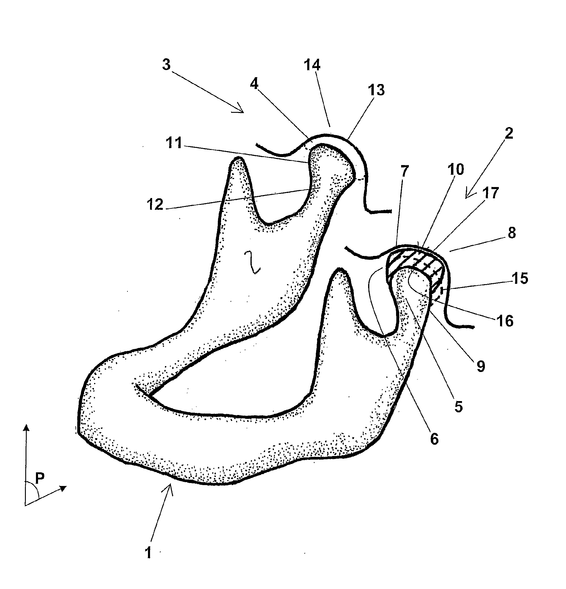
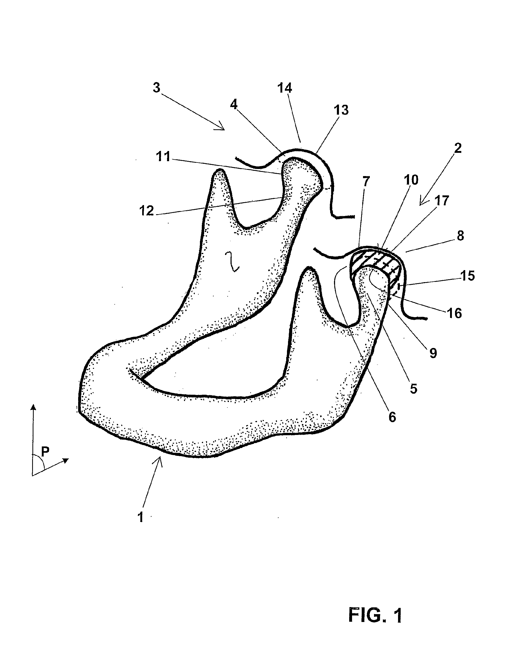
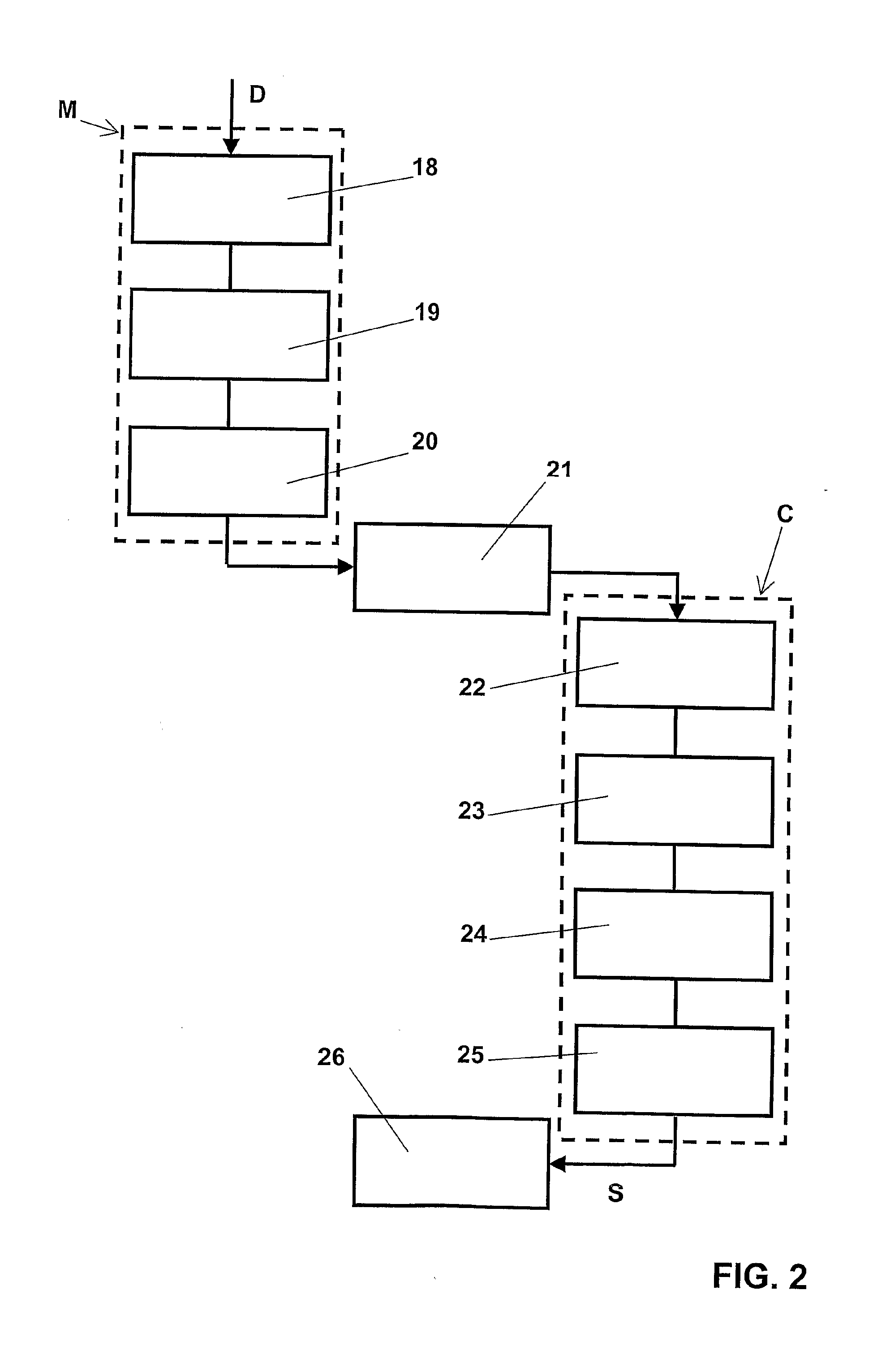
[0036]The references to FIGS. 1 and 2 will serve to explain in detail the features of the prosthetic temporomandibular implant 1 according to the invention, and those of the corresponding production method.

[0037]FIG. 1 shows a simplified transcription of a three-dimensional representation of a human mandible 1 like that generated by a piece of software for processing data produced by a medical imaging device.

[0038]This device is a system capable of providing a highly precise image of the part of the human body in question, for example a tomograph or a magnetic resonance imaging (MRI) device.

[0039]The format of the data output from this system is often of a so-called “proprietary” nature, but more and more frequently tends to adhere to the DICOM (“Digital Imaging and Communication in Medicine”) standard.

[0040]The MIMICS® software from the company Materialise, for example, is capable of processing the data resulting from a cranial examination by any scanner using the DICOM standard, a...


PUM

PropertyMeasurementUnit
thickaaaaaaaaaa
medical imagingaaaaaaaaaa
shapeaaaaaaaaaa

Abstract

The prosthetic temporomandibular implant (10) comprises a concave surface (16) and a convex surface (17) designed to cooperate, respectively, with the natural outer surface (9) of the condyle (5) and the natural inner surface (7) of the fossa (8) of a damaged joint (2) of a human mandible (1). It is made of a rigid biocompatible material such as ceramic, stainless steel or an aluminum / zirconium alloy.The implant is designed based on an image of the joint (2) generated by a medical imaging system and incorporating an image of a healthy joint (3); these three-dimensional images are processed by a CAD (segmentation, vectorization) system to obtain a vector representation of the implant (10) and a data file capable of controlling a digital milling machine.The invention is applicable to the restoration of a damaged TMJ (2).

Description

TECHNICAL FIELD OF THE INVENTION[0001]The present invention relates to a prosthetic implant for reconstructing a temporomandibular joint that has become non-functional, and a method for producing this implant.TECHNOLOGICAL BACKGROUND OF THE INVENTION[0002]A comprehensive analysis of the specific characteristics of a temporomandibular joint, also known as a temporomaxillary joint, as compared to the other diarthroses of the human body, is made in French patent application FR 2,558,721 in the name of the company Landos—Application Orthopédique Francaise, published on Aug. 2, 1985, in the preamble to the description of a prosthesis for a joint of this type.[0003]The temporomandibular joint (abbreviated TMJ) is delimited by a cranial articular surface underlying the temporal bone and by an articular surface overlying the mandible. The glenoid fossa of the TMJ is pellucid since the bony layer that isolates the fossa from the overlying cranial mass is between several tenths of a millimete...

Claims


Application Information

Patent Timeline
Patent Type & Authority Applications(United States)
IPC IPC(8): A61F2/30G06F17/00
CPCA61F2/30942A61F2/3099A61F2002/3092Y10T29/49995A61L27/02Y10T29/49996A61F2002/30948B33Y80/00
Inventor DEFFRENNES, DOMINIQUE
Owner OBL
Learn More