High bypass-ratio turbofan jet engine

a turbofan and high bypass ratio technology, applied in liquid fuel engines, machines/engines, combustion air/fuel air treatment, etc., can solve the problems of large fan diameter, large fan, and high bypass ratio, and achieve high bypass ratio turbofan, reduce air resistance acting on the engine, and increase the bypass ratio without increasing the fan diameter

Inactive Publication Date: 2009-09-10
JAPAN AEROSPACE EXPLORATION AGENCY
View PDF8 Cites 37 Cited by
  • Summary
  • Abstract
  • Description
  • Claims
  • Application Information

AI Technical Summary

Benefits of technology

[0007]The present invention has been contrived in view of such problems of the prior art, and an object of the present invention is to provide a high bypass-rat

Problems solved by technology

Therefore, an engine with high bypass ratio tends to have improved fuel consumption and generate low jet noise.
However, an engine with a larger fan has the following problems.
First, the weight of moving and stationary blades and fan case/nacelle is large.
Secondly, due to the large engine diameter, the main landing gears need to be made long to maintain a predetermined or more distance between the ground and the engines in the case of aircraft with the engines beneath the wings.
In this turbofan jet engine, however, it is considered that, when thrust is increased to a predetermined level or higher, the impact of increase in weight of the speed reduction mechanism and its lubrication system or the loss of shaft p

Method used


Image

  • High bypass-ratio turbofan jet engine
  • High bypass-ratio turbofan jet engine
  • High bypass-ratio turbofan jet engine

Examples


embodiment 1

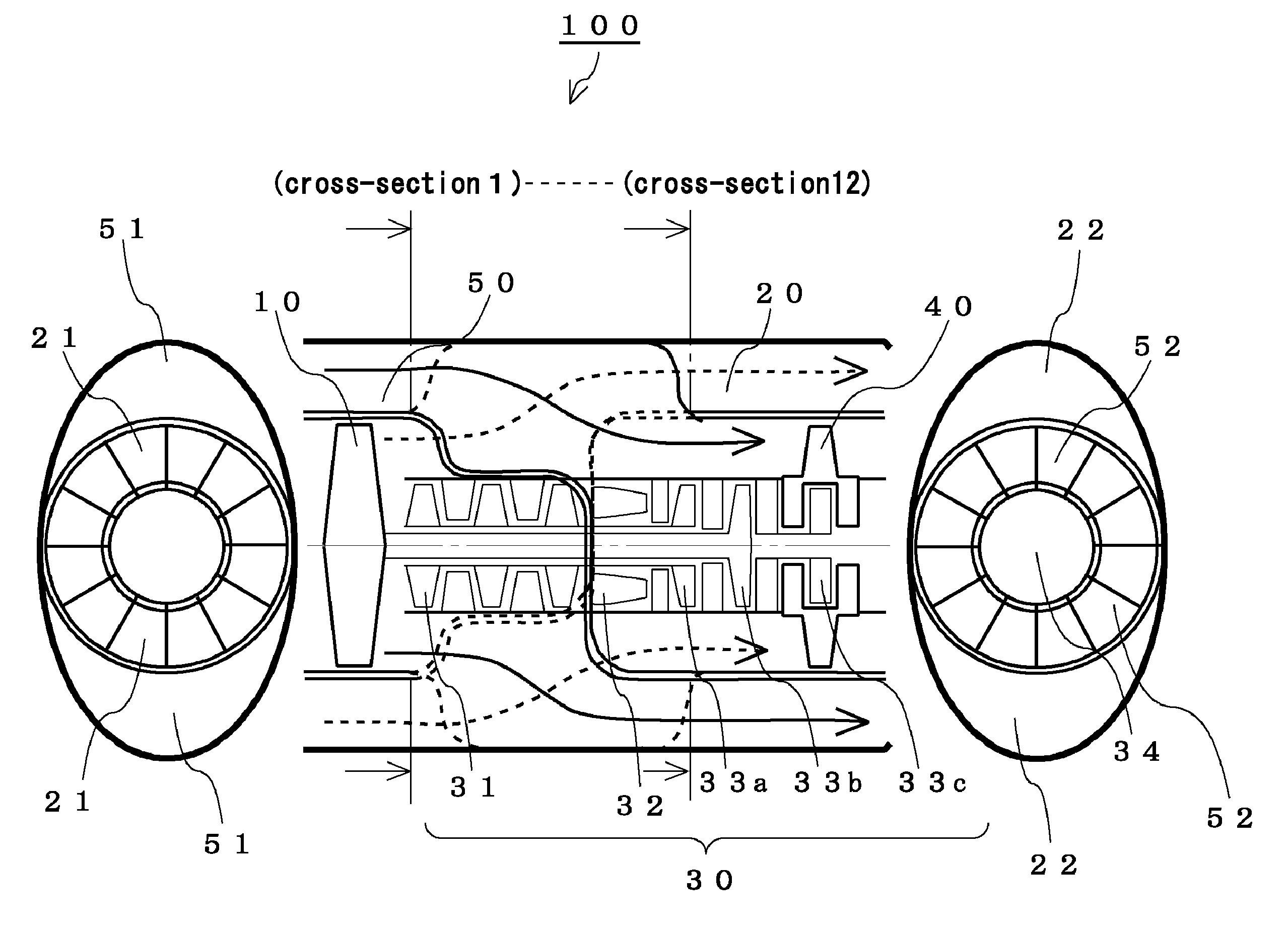
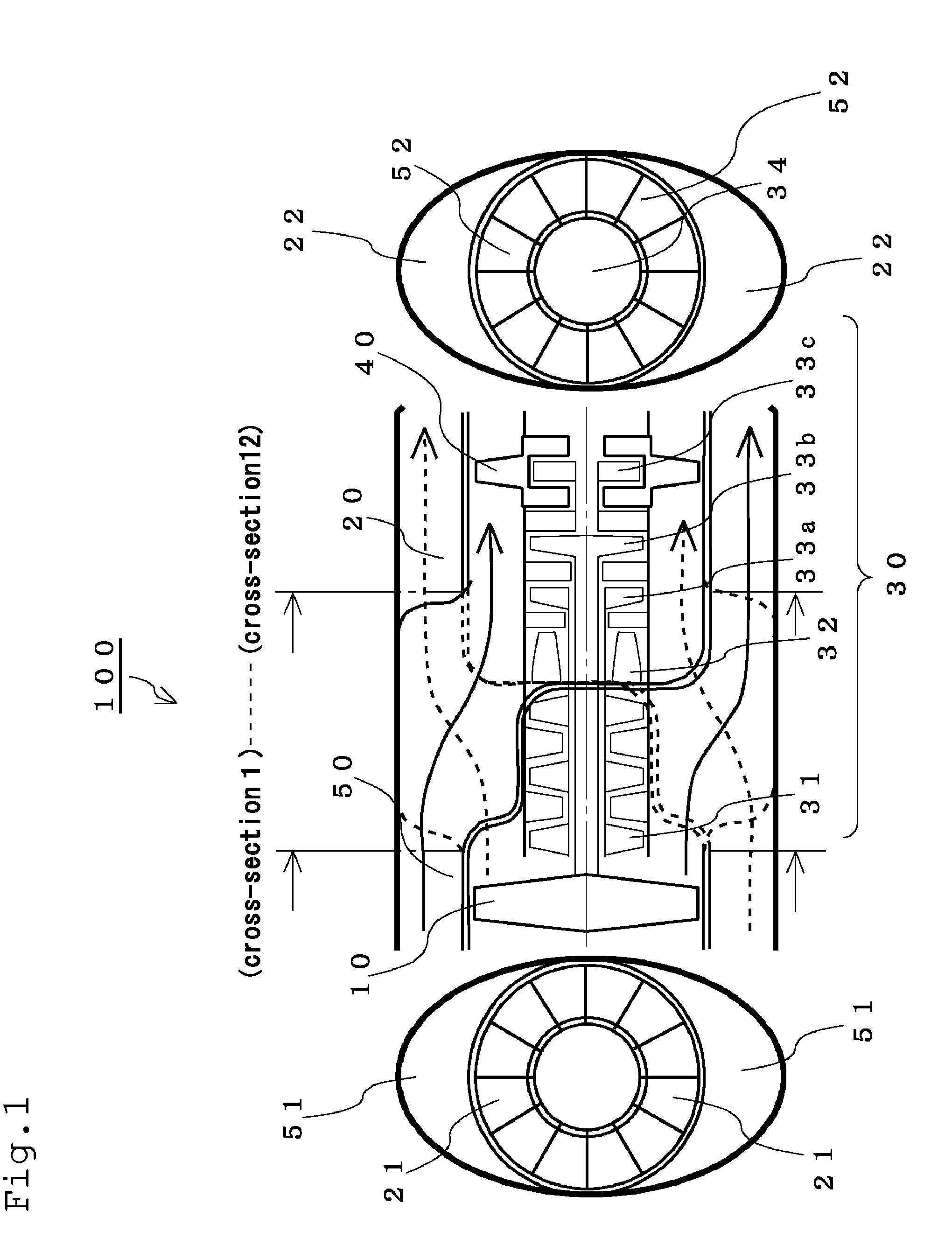
[0026]FIG. 1 is an explanatory diagram showing a turbofan jet engine 100 according to Embodiment 1 of the present invention. For the convenience of explanation, the turbofan jet engine 100 is illustrated in the shape of a vertically long ellipse, but this engine is actually in the shape of a horizontally long ellipse.

[0027]This turbofan jet engine 100 has: a core engine 30 constituted by a compressor 31, a combustor 32, turbines 33 and an exhaust nozzle 34; a front fan 10 which is positioned upstream of the core engine; a front fan duct 20 which leads air compressed by the front fan 10 but bypassing the core engine to the outside; and aft fan 40 which is positioned downstream of the core engine; and an aft fan duct 50 which introduces the air into the aft fan 40.

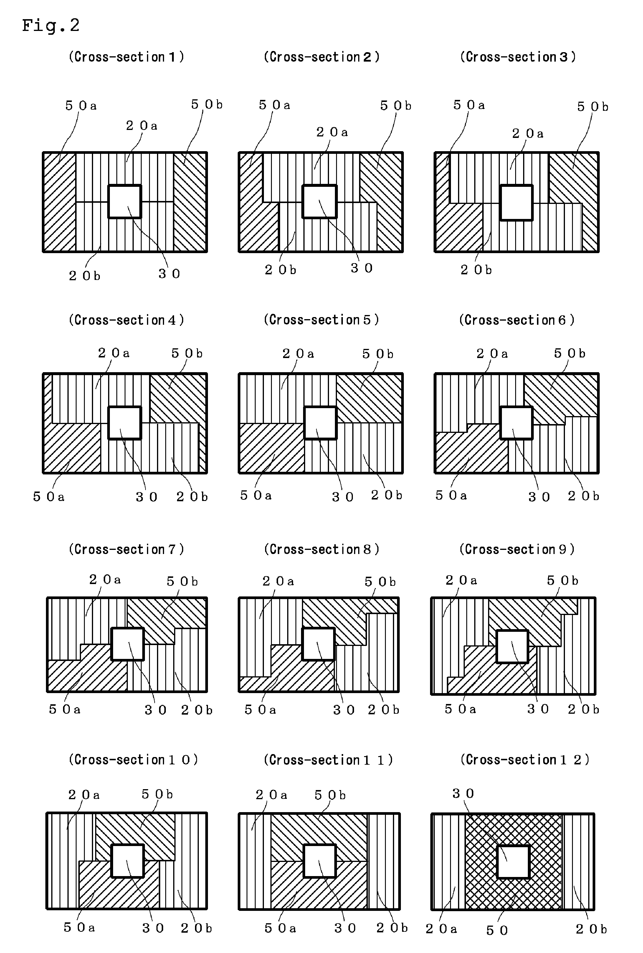
[0028]Although described in detail later with reference to FIG. 2, the front fan duct 20 and the aft fan duct 50 are disposed along the core engine 30 such as to change the cross-sectional shapes of the front fan duct 20 and...

embodiment 2

[0042]FIG. 4 is an explanatory diagram showing a turbofan jet engine 200 according to Embodiment 2.

[0043]This entire turbofan jet engine 200 is embedded in a main wing. Also, when viewing the aircraft from front, the air intake 21 of the front fan 10 and the air intake 51 of the aft fan 40 are independently provided away from each other.

[0044]FIG. 5 is an explanatory diagram showing an example of how the cross-sectional shapes of the front fan duct 20 and of aft fan duct 50 of Embodiment 2 change.

[0045]As with the case of Embodiment 1, as viewed from the upstream side, the front fan duct 20 and aft fan duct 50 change their positions, shapes and size gradually in a counterclockwise direction around the core engine 30 by moving toward the downstream side. Note that the sum of the cross-sectional area of the front fan duct 20 and the cross-sectional area of the aft fan duct 50 may be constant as in Embodiment 1, or may be changed without having these ducts protrude from the main wing. ...


PUM


Abstract

To provide a turbofan jet engine which is capable of increasing the bypass ratio without increasing the fan diameter, and of reducing air resistance acting on the engine, a front fan duct that discharges air compressed by a front fan to the atmosphere and an aft fan duct that introduces air into an aft fan are disposed such as to change cross-sectional shapes thereof by rotating around a core engine in a counterclockwise direction, so that the cross-sectional geometric relationship between the front fan duct and the aft fan duct at a position immediately posterior to the front fan and a cross-sectional geometric relationship between the front fan duct and the aft fan duct at a position immediately anterior to the aft fan are inverted.

Description

BACKGROUND OF THE INVENTION[0001]1. Field of the Invention[0002]The present invention relates to a high bypass-ratio turbofan jet engine, and more particularly to a high bypass-ratio turbofan jet engine which is capable of increasing the bypass ratio without increasing the fan diameter, and of reducing air resistance acting on the engine.[0003]2. Description of the Related Art[0004]In a turbofan jet engine that is widely used in aircraft flying at subsonic speeds, generally, the larger the ratio between the quantity of air passing through a core part and the quantity of air passing through a fan part (bypass ratio), the closer the exhaust velocity to the cruising speed and the higher the propulsion efficiency. Therefore, an engine with high bypass ratio tends to have improved fuel consumption and generate low jet noise. However, an engine with a larger fan has the following problems. First, the weight of moving and stationary blades and fan case / nacelle is large. Secondly, due to th...

Claims


Application Information

Patent Timeline
IPC IPC(8): F01D25/24
CPCB64C7/02B64D29/02F05D2250/14F02K3/065Y02T50/671F02C7/04Y02T50/60
Inventor YANAGI, RYOJIFUJIWARA, HITOSHI
Owner JAPAN AEROSPACE EXPLORATION AGENCY
Why Eureka
Try Eureka