Three-dimensional Imaging System

a three-dimensional imaging and imaging system technology, applied in the field of dentistry, can solve the problems of high cost, no diagnostic function, and high restriction on the surface conditions to obtain high-quality images, and achieve the effects of high productivity, patient comfort, and convenien

Inactive Publication Date: 2009-09-10
CAO GROUP
View PDF7 Cites 36 Cited by
  • Summary
  • Abstract
  • Description
  • Claims
  • Application Information

AI Technical Summary

Benefits of technology

[0005]The system is intended to take dental restoration to a high level of productivity, patient comfort, and convenience with its 3D CAD/CAM restorative sys

Problems solved by technology

The surface conditions are also highly restricted to obtain high quality images.
These system

Method used


Image

  • Three-dimensional Imaging System
  • Three-dimensional Imaging System
  • Three-dimensional Imaging System

Examples


Embodiment Construction

[0015]With reference now to the drawings, the preferred embodiment of the three-dimensional scanner is herein described. It should be noted that the articles “a”, “an”, and “the”, as used in this specification, include plural referents unless the content clearly dictates otherwise.

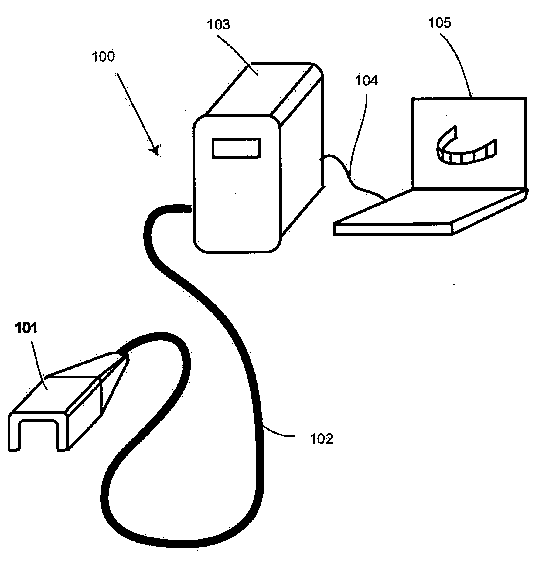
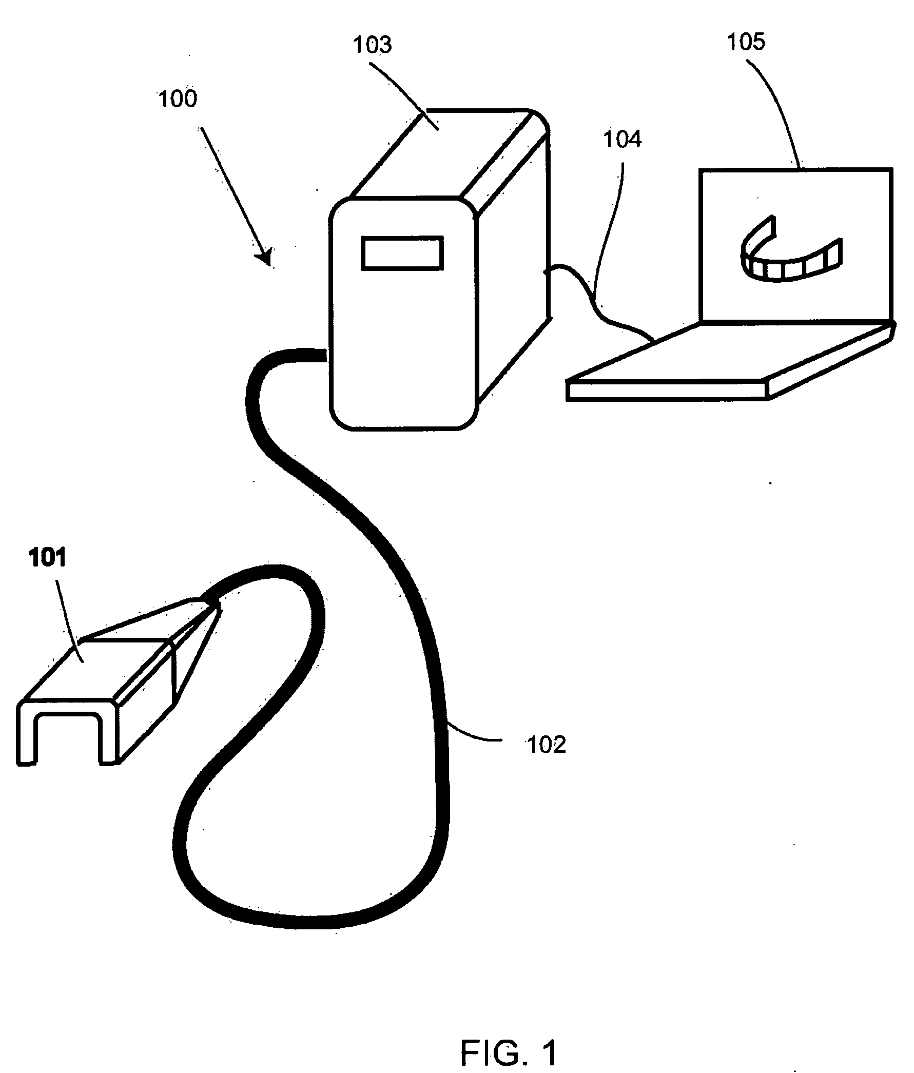
[0016]With reference to FIG. 1, 100 is the system itself while 101 is a hand probe with a three-dimensional scanning head. Cable 102 contains both optical fiber and electrical cables inside. Processing consol 103 includes controls for scanning heads, light sources, CCD cameras, and process CPU. Processing consol 103 is connected to computer 105 by cable 104. Computer 105 is provided with customized software for imaging processing. U8i

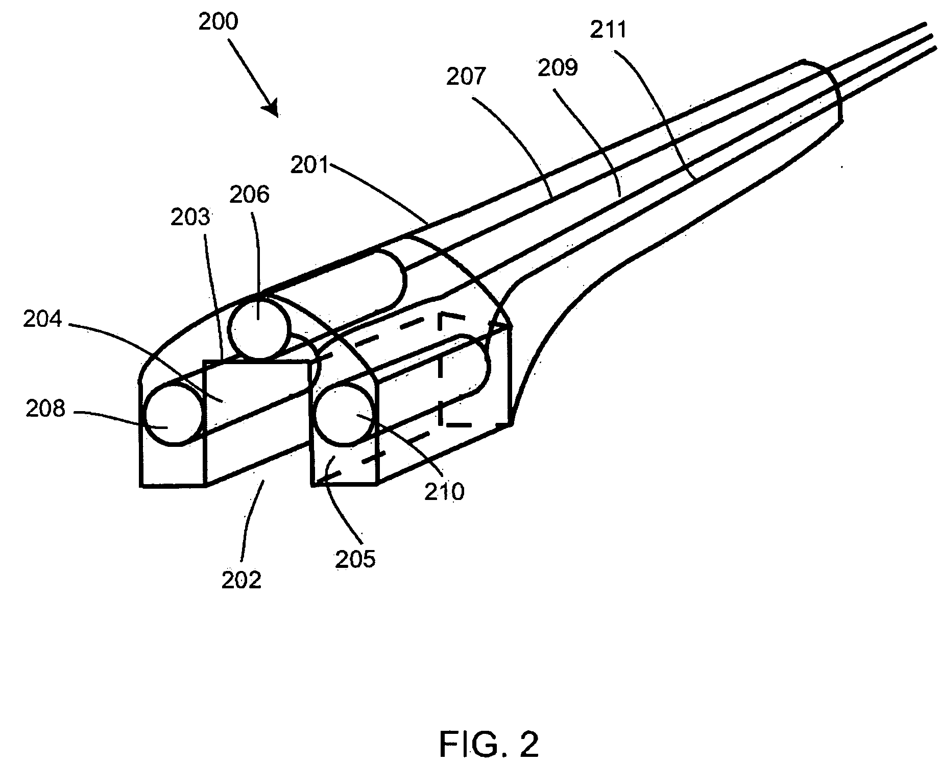
[0017]FIG. 2 depicts the hand probe (FIG. 1, 101) used in the present invention, where 200 is the hand probe. Housing 201 provides open space 202 surrounded by three walls 203, 204, and 205, respectively. The open space 202 is sufficient to allow the probe 200 to encompass the...


PUM


Abstract

The present invention is a three-dimensional scanner for use in the oral cavity. The scanner of the present invention utilizes three optical scanners in a single-hand wand to create three-dimensional images with a single pass of the wand over the area scanned. Processing of the collected images is then composited into a three-dimensional image for CAD/CAM restoration and diagnostic aid in dentistry. OCT technology may be utilized to generate the images.

Description

FIELD OF THE INVENTION[0001]The present invention relates to the field of dentistry and more particularly relates to a three-dimensional tomography system for imaging and diagnosing the oral cavity features contained within.BACKGROUND OF THE INVENTION[0002]Three-dimensional image systems including image scanning, image computer processing, and machining of processed image have been widely used in dentistry and other fields. The key area is the imaging scanning process. Several products like CEREC™ by Sirona, E4D™ for Dentist and E4D™ for Laboratory by D4D Tech, ETREO™ by Cadent, Lava™ by 3M have used a laser scanning method or CCD to catch the image of the surface scanned and use proprietary algorithms to build three-dimensional images. Such systems require multiple scans in different directions in order to build three-dimensional images. The surface conditions are also highly restricted to obtain high quality images. These systems, then, can only generate three-dimensional images a...

Claims


Application Information

Patent Timeline
IPC IPC(8): A61B6/00
CPCA61B5/0066A61B5/0088A61B2562/028G06T7/0065G06T2207/30036G06T2207/10028G06T2207/10101G06T2207/20088G06T2207/10012G06T7/55
Inventor CAO, DENSENLIN, ZHAO-HUI
Owner CAO GROUP
Why Eureka
Try Eureka