Laminated body for manufacturing resin mold, laminated body, resin mold and method for manufacturing magnetic recording medium

a technology of resin molds and resin molds, which is applied in the direction of electric/magnetic/electromagnetic heating, transportation and packaging, coatings, etc., can solve the problems of deterioration of snr, deterioration of bit error rate, and magnetization volume per bit, and achieve high level of productivity, superior precision, and the effect of manufacturing with comparative eas

Active Publication Date: 2015-02-17
RESONAC CORP
View PDF17 Cites 0 Cited by
  • Summary
  • Abstract
  • Description
  • Claims
  • Application Information

AI Technical Summary

Benefits of technology

[0066]The laminated body for manufacturing a resin mold according to the present invention enables a resin replica mold which has a fine pattern of protrusions and recesses formed thereon to be manufactured with superior precision, in large quantities, and at a high level of productivity.
[0067]The method for manufacturing a laminated body for manufacturing a resin mold according to the present invention enables the above laminated body to be manufactured with comparative ease.
[0068]The method for manufacturing a resin mold according to the present invention enables a resin replica mold having a fine pattern which has recessed and protruding portions and is formed on the mold to be manufactured with superior precision, in large quantities, and at a high level of productivity. Accordingly, in the manufacture of semiconductors or the like using a nanoimprint method, the mass producibility of the product can be improved, and the manufacturing costs can be reduced.
[0069]The method for manufacturing a magnetic recording medium according to the present invention enables a magnetic recording medium that is capable of realizing a high recording density to be manufactured inexpensively and at a high level of productivity.

Problems solved by technology

However, as the track density is increased, mutual interference tends to occur between the magnetically recorded information within adjacent tracks, and the resulting magnetized transition region in the boundary region between the tracks acts as a noise source, causing problems such as a deterioration in the SNR.
This reduced SNR leads directly to a deterioration of the bit error rate, and is therefore an impediment to achieving increased recording densities.
However, as the recording bits are reduced in size, the minimum magnetization volume per bit is reduced, and a problem arises in that recording data may be erased due to magnetization reversal caused by heat fluctuation.
Although this method enables inter-track effects to be suppressed to a minimum, achieving a satisfactory reproduction output level can be difficult, and therefore ensuring an adequate SNR is also difficult.
However, the shape of the pattern of protrusions and recesses formed on the substrate is inherited by the subsequently deposited films, and as a result, a problem arises in that the floating position and floating height of the recording / reproducing head that performs recording or reproduction while floating across the surface of the medium cannot be stabilized.
The mold for nanoimprinting is, for example, a mold prepared by forming an ultra fine pattern which has recessed and protruding portions and is 100 nm or less in the surface of a silicon material or the like, and is very expensive.
If this mold suffers abrasion or damage during the imprint process, then the mold must be replaced, which results in an increase in the manufacturing cost of the magnetic recording medium product or semiconductor or the like manufactured using the nanoimprint method.
However formation of a finer pattern on the nanoimprint mold tends to accelerate abrasion of the mold and increase the frequency of mold damage.
However, if this viscosity of the curable resin increases, then the ability of the resin to fill the gaps within the pattern of protrusions and recesses during pattern transfer from the master mold tends to deteriorate, resulting in a deterioration in the precision of the transfer.
However, this method tends to require large manufacturing equipment, and has a low level of productivity.
Moreover, obtaining a uniform thin layer using this type of method tends to be difficult.
Furthermore, yet another method involves using spin coating to form a thin film of a curable resin on a base film, and then using this thin film as the transfer material into which the master mold is pressed, but this method tends to require even larger manufacturing equipment, and suffers from inferior productivity.
Accordingly, the productivity cannot be improved with these methods, and the precision of the pattern transfer may deteriorate.
As a result, if a semiconductor is manufactured using the nanoimprint method, then in a similar manner, the productivity of the semiconductor cannot be improved, and the precision of the pattern transfer tends to deteriorate.
Moreover, if a magnetic recording medium is manufactured using the nanoimprint method, then the recording density of the magnetic recording medium tends to worsen, and the productivity may deteriorate.

Method used


Image

  • Laminated body for manufacturing resin mold, laminated body, resin mold and method for manufacturing magnetic recording medium
  • Laminated body for manufacturing resin mold, laminated body, resin mold and method for manufacturing magnetic recording medium
  • Laminated body for manufacturing resin mold, laminated body, resin mold and method for manufacturing magnetic recording medium

Examples


examples

[0244]The present invention is described in more detail below using a series of examples, although the present invention is in no way limited by these examples.

Example of the First and Second Aspects

Preparation of curable resin material

[0245]77.4 parts by mass of BEAMSET 371 (an acrylic monomer, manufactured by Arakawa Chemical Industries, Ltd.), 6.0 parts by mass of a 25% by mass acetone solution of IRGACURE 127 (a photopolymerization initiator, manufactured by Ciba Specialty Chemicals Inc.), 2.5 parts by mass of MEGAFAC R-30 (a fluorine-containing surfactant, manufactured by DIC Corporation) and 16.4 parts by mass of ethyl acetate (a diluent solvent) were combined and blended together to form a solution of an ultraviolet-curable resin material.

[0246]The viscosity of this curable resin material was 59.1 mPa·s, and following curing, the cured product exhibited a light transmittance of 65% for radiation of wavelength 365 nm, and a tensile elastic modulus at a temperature of 25° C. of...


PUM

PropertyMeasurementUnit
viscosityaaaaaaaaaa
tensile elastic modulusaaaaaaaaaa
temperatureaaaaaaaaaa

Abstract

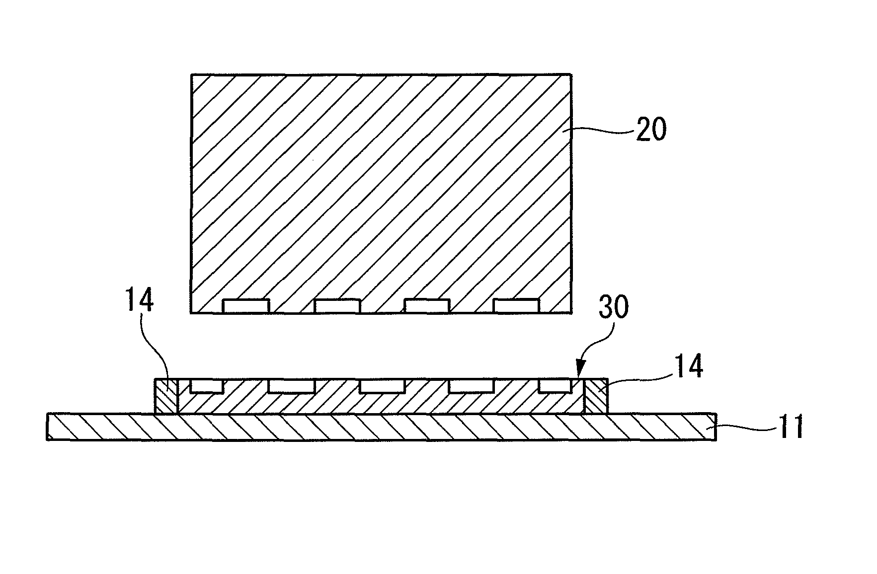
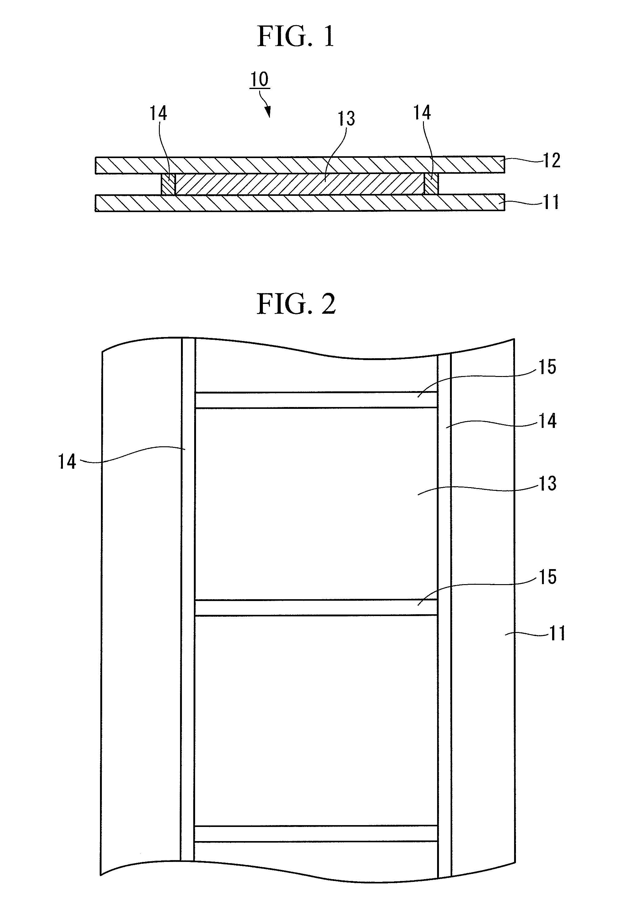
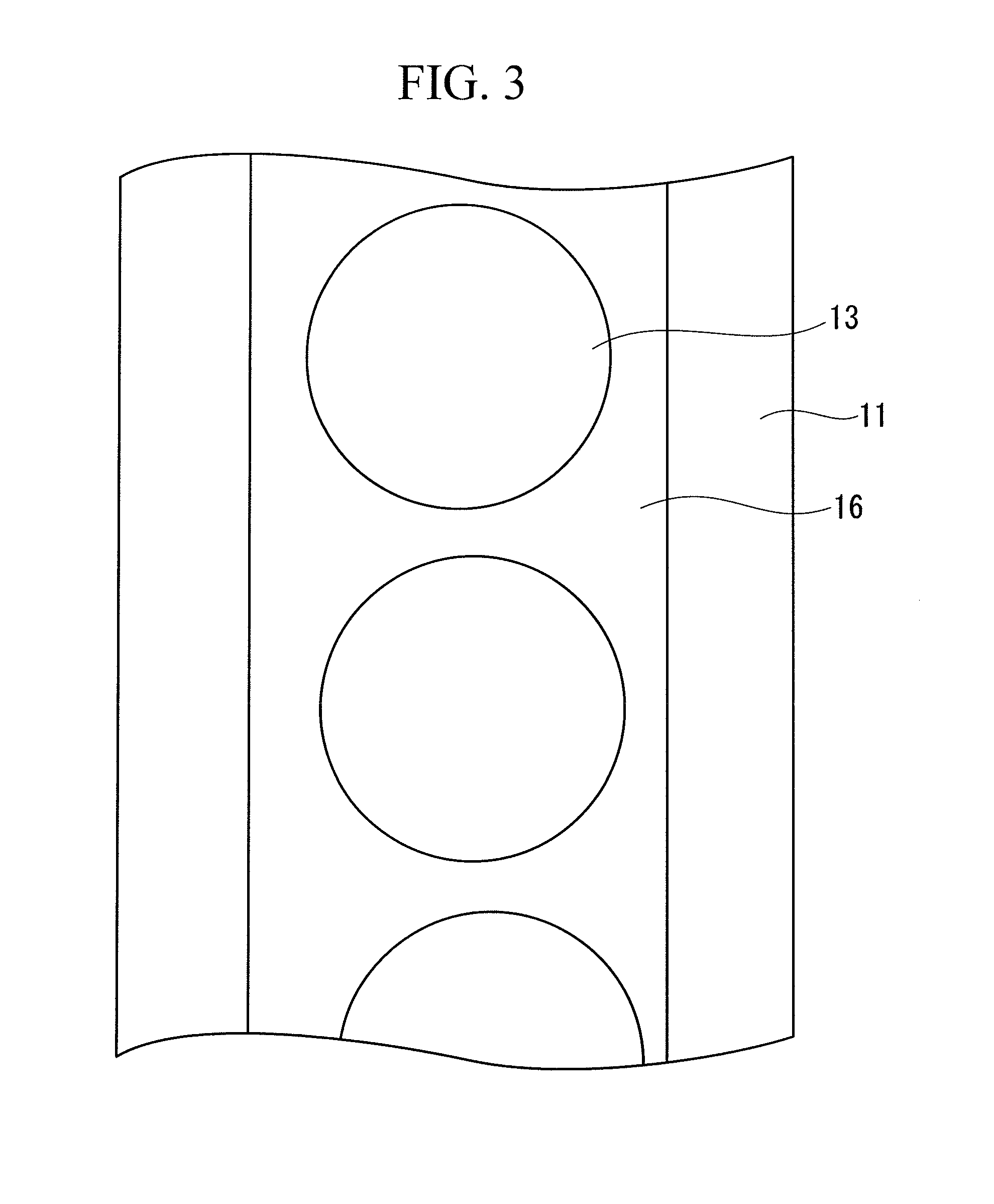
A laminated body which forms a resin mold by compression molding using a master mold, the laminated body having: a pair of mutually facing base materials, a layer of a liquid or gel-like curable resin material sandwiched between the pair of base materials, and one or more flow suppression bodies, which are composed of a cured product of the curable resin material and are sandwiched between the pair of base materials, wherein the layer of the curable resin material is sealed by the pair of base materials and the flow suppression bodies. Also, a method for manufacturing a resin mold using the laminated body.

Description

TECHNICAL FIELD[0001]The present invention relates to a laminated body for manufacturing a resin mold and a method for manufacturing the same, as well as a method for manufacturing a resin mold and a method for manufacturing a magnetic recording medium.[0002]Priority is claimed on Japanese Patent Application No. 2008-135989 and Japanese Patent Application No. 2008-135990, both filed May 23, 2008, the contents of which are incorporated herein by reference.BACKGROUND ART[0003]In fields such as semiconductor manufacturing, nanoimprint methods have begun to attract considerable attention as a technology that is capable of forming ultra fine patterns of 100 nm or less and providing excellent mass production applicability at minimal cost. In a nanoimprint method, a mold which has a pattern of protrusions and recesses to be transferred is pressed against a transfer target material composed of a photocurable resin or a thermosetting resin, and the transfer target material is then cured by t...

Claims


Application Information

Patent Timeline
Patent Type & Authority Patents(United States)
IPC IPC(8): B05D5/00B29C33/38B29C33/42G11B5/855
CPCG11B5/855B29C33/3842B29C33/424Y10T428/31663
Inventor UCHIDA, HIROSHIUMEZAWA, TOMOKAZUFUKUSHIMA, MASATOTAKEYAMA, SHUNSUKESAKURAGI, TAKANORI
Owner RESONAC CORP
Why Eureka
Try Eureka